GB Table Saw Instruction manual F Banc de scie Manuel d instructions D Tischsäge Betriebsanleitung I Banco sega Istruzioni per l uso NL Zaagtafel
|
|
|
- Lieven de Backer
- 8 jaren geleden
- Aantal bezoeken:
Transcriptie
1 GB Table Saw Instruction manual F Banc de scie Manuel d instructions D Tischsäge Betriebsanleitung I Banco sega Istruzioni per l uso NL Zaagtafel Gebruiksaanwijzing E Sierra de mesa Manual de instrucciones P Serra de Mesa Manual de instruções DK Stationær rundsav Brugsanvisning S Bordsåg Bruksanvisning N Bordsag Bruksanvisning SF Pöytäpyörösaha Käyttöohje GR Τραπέζι πριονίσµατος Οδηγίες χρήσης 2704

2 2 525 mm 620 mm 1 25 mm

3 (A) (B) 9 10 ON OFF

4

5 mm A B

6 300mm 120mm 130mm 42 6mm 50mm 7 130mm 300mm mm 50mm 44 8mm 50mm 100mm mm 19mm 120mm 40mm 1 460mm 140mm

7

8
9 ENGLISH 1. Hole diameter 8 mm 2. 6 mm Std. washer 3. No.10 wood screw 40 mm min. length 4. 6 mm Mounting bolt & Nut tighten securely 5. Miter gauge 6. Rip fence 7. Handle 8. Lock lever 9. Arrow pointer 10. Handwheel Adjusting screw Adjusting screw 13. Switch 14. Padlock 15. Lever 16. Sub table (R) 17. Scale plate 18. Screw 19. Sub table (back) 20. Sub table (L) SPECIFICATIONS Explanation of general view 21. Offset wrench 22. Hex nut 23. Wrench 24. Inner flange 25. Ring 26. Saw blade 27. Outer flange 28. Blade guard 29. Riving knife 30. Blade guard mounting portion (stay) 31. Blade 32. These two clearances should be equal. 33. Hex bolts (B) 34. Hex bolts (A) 35. Hook 36. Knob 37. Guide rail 38. Scale 39. Hex bolts 40. Guideline 41. Screws 42. Face/edge parallel 43. Wood screw 44. Glue together 45. No. 10 wood screws (long enough to penetrate halfway into facing) 46. Push stick 47. Auxiliary fence 48. Push block 49. CROSS CUTTING 50. MITERING 51. BEVEL CUTTING 52. COMPOUND MITERING (ANGLES) 53. Small plate 54. Screw for positive stop 55. Groove 56. Limit mark 57. Brush holder cap 58. Screwdriver Model 2704 (for European countries) (for other than European countries) Arbor hole 30 mm 25 mm Blade diameter 260 mm 255 mm Max. cutting mm 91 mm capacities mm 63 mm No load speed (min -1 ) 4,800 Table size (L x W) Dimensions (L x W x H) with table(s) not extended (665 mm 1,045 mm) x (753 mm 1,066 mm) with sub tables (R) and (back) 715 mm x 753 mm x 344 mm with sub tables (R) and (back) 567 mm x (753 mm 1,066 mm) with sub table (R) 665 mm x 753 mm x 344 mm with sub table (R) Net weight 36 kg 30 kg Safety class /II Due to our continuing program of research and development, the specifications herein are subject to change without notice. Note: Specifications may differ from country to country. 9
 31. Blade 32. These two clearances should be equal. 33. Hex bolts (B) 34. Hex bolts (A) 35. Hook 36. Knob 37. Guide rail 38. Scale 39. Hex bolts 40. Guideline 41.")
10 Symbols The following show the symbols used for the tool. Be sure that you understand their meaning before use.... Read instruction manual.... DOUBLE INSULATION... Wear safety glasses.... Do not place hand or fingers close to the blade. Intended use The tool is intended for cutting in wood. Power supply The tool should be connected only to a power supply of the same voltage as indicated on the nameplate, and can only be operated on single-phase AC supply. They are double-insulated in accordance with European Standard and can, therefore, also be used from sockets without earth wire. ADDITIONAL SAFETY RULES FOR TOOL SAVE THESE INSTRUCTIONS. 1. Wear eye protection. 2. Don't use the tool in presence of flammable liquids or gases. 3. NEVER use the tool with an abrasive cut-off wheel installed. 4. Check the blade carefully for cracks or damage before operation. Replace cracked or damaged blade immediately. 5. Use only saw blades recommended by the manufacturer and which conform to EN847-1, and observe that the riving knife must not be thicker than the width of the cut by the saw blade and not thinner than the body of the blade. 6. Always use accessories recommended in this manual. Use of improper accessories such as abrasive cut-off wheels may cause an injury. 7. Select the correct saw blade for the material to be cut. 8. Do not use saw blades manufactured from high speed steel. 9. To reduce the emitted noise, always be sure that the blade is sharp and clean. 10. Use correctly sharpened saw blades. Observe the maximum speed marked on the saw blade. 11. Clean the spindle, flanges (especially the installing surface) and hex nut before installing the blade. Poor installation may cause vibration/wobbling or slippage of the blade. 12. Use saw-blade guard and riving knife for every operation for which it can be used, including all through sawing operations. Always install the blade guard following the instructions out-lined in this manual. Through sawing operations are those in which the blade cuts completely through the workpiece as in ripping or cross cutting. NEVER use the tool with a faulty blade guard or secure the blade guard with a rope, string, etc. Any irregular operation of the blade guard should be corrected immediately. 13. Immediately reattach the guard and riving knife after completing an operation which requires removal of the guard. 14. Do not cut metals such as nails and screws. Inspect for and remove all nails, screws and other foreign matter from the workpiece before operation. 15. Remove wrenches, cut-off pieces, etc. from the table before the switch is turned on. 16. NEVER wear gloves during operation. 17. Keep hands out of the line of the saw blade. 18. NEVER stand or permit anyone else to stand in line with the path of the saw blade. 19. Make sure the blade is not contacting the riving knife or workpiece before the switch is turned on. 20. Before using the tool on an actual workpiece, let it run for a while. Watch for vibration or wobbling 10

11 that could indicate poor installation or a poorly balanced blade. 21. The tool should not be used for slotting, rabbetting or grooving. 22. Replace table insert when worn. 23. NEVER make any adjustments while tool is running. Disconnect tool before making any adjustments. 24. Use a push stick when required. Push sticks MUST be used for ripping narrow workpieces to keep your hands and fingers well away from the blade. 25. Always store the push-stick when it is not in use. 26. Pay particular attention to instructions for reducing risk of KICKBACK. KICKBACK is a sudden reaction to a pinched, bound or misaligned saw blade. KICKBACK causes the ejection of the workpiece from the tool back towards the operator. KICKBACKS CAN LEAD TO SERIOUS PERSONAL INJURY. Avoid KICKBACKS by keeping the blade sharp, by keeping the rip fence parallel to the blade, by keeping the riving knife and blade guard in place and operating properly, by not releasing the workpiece until you have pushed it all the way past the blade, and by not ripping a workpiece that is twisted or warped or does not have a straight edge to guide along the fence. 27. Do not perform any operation freehand. Freehand means using your hands to support or guide the workpiece, in lieu of a rip fence or miter gauge. 28. NEVER reach around or over saw blade. NEVER reach for a workpiece until the saw blade has completely stopped. 29. Avoid abrupt, fast feeding. Feed as slowly as possible when cutting hard workpieces. Do not bend or twist workpiece while feeding. If you stall or jam the blade in the workpiece, turn the tool off immediately. Unplug the tool. Then clear the jam. 30. NEVER remove cut-off pieces near the blade or touch the blade guard while the blade is running. 31. Knock out any loose knots from workpiece BEFORE beginning to cut. 32. Don't abuse cord. Never yank cord to disconnect from receptacle. Keep cord away from heat, oil, water and sharp edges. 33. Some dust created from operation contains chemicals known to cause cancer, birth defects or other reproductive harm. Some examples of these chemicals are: - lead from lead-based-painted material and, - arsenic and chromium from chemically-treated lumber. - Your risk from these exposures varies, depending on how often you do this type of work. To reduce your exposure to these chemicals: work in a well ventilated area and work with approved safety equipment, such as those dust masks that are specially designed to filter out microscopic particles. 34. Connect the tool to a dust-collecting device when sawing. 35. The guard can be lifted during workpiece setup and for ease of cleaning. Always make sure that guard hood is down and flat against sawtable before plugging in the tool. SAVE THESE INSTRUCTIONS INSTALLATION Positioning table saw (Fig. 1 3) Locate the table saw in a well lit and level area where you can maintain good footing and balance. It should be installed in an area that leaves enough room to easily handle the size of your workpieces. The table saw should be secured with four screws or bolts to the work bench or table saw stand using the holes provided in the bottom of the table saw. When securing the table saw on the work bench, make sure that there is an opening in the top of the work bench the same size as the opening in the bottom of the table saw so the sawdust can drop through. If during operation there is any tendency for the table saw to tip over, slide or move, the work bench or table saw stand should be secured to the floor. Storing accessories (Fig. 4 & 5) The miter gauge, blade and wrenches can be stored on the left side of the base and the rip fence can be stored at the right side of the base. The blade guard to be removed in dado cutting can be stored at the right hand rear. FUNCTIONAL DESCRIPTION Always be sure that the tool is switched off and unplugged before adjusting or checking function on the tool. Adjusting the depth of cut (Fig. 6) The depth of cut may be adjusted by turning the handle. Turn the handle clockwise to raise the blade or counterclockwise to lower it. NOTE: Use a shallow depth setting when cutting thin materials in order to obtain a cleaner cut. Adjusting the bevel angle (Fig. 7) Loosen the lock lever counterclockwise and turn the handwheel until the desired angle (0 45 ) is obtained. The bevel angle is indicated by the arrow pointer. After obtaining the desired angle, tighten the lock lever clockwise to secure the adjustment. After adjusting the bevel angle, be sure to tighten the lock lever securely. 11

12 Adjusting positive stops The tool is equipped with positive stops at 90 and 45 to the table surface. To check and adjust the positive stops, proceed as follows: (Fig. 8) Move the handwheel as far as possible by turning it. Place a triangular rule on the table and check to see if the blade is at 90 or 45 to the table surface. If the blade is at an angle shown in Fig. A, turn the adjusting screws clockwise; if it is at an angle shown in Fig. B, turn the adjusting screws counterclockwise to adjust the positive stops. (Fig. 9) After adjusting the positive stops, set the blade at 90 to the table surface. Then adjust the arrow pointer so that its right edge is aligned to the 0 graduation. (Fig. 10) Switch action For the lever type switch Before plugging in the tool, always be sure that the tool is switched off. To start the tool, raise the switch lever. To stop it, lower the switch lever. (Fig. 11) The hinged switch lever plate can be locked by passing padlock through the hasp on the left hand side. (Fig. 12) For the button type switch (Fig. 13) Before operation, make sure that the tool is turned on and off. To start the tool, press the ON ( I ) button. To stop it, press the OFF ( O ) button. Sub table (R) This tool is provided with the sub table (R) on the right side of the main table. To use the sub table (R), raise both levers on the front right side, pull out the table (R) fully and then lower the levers to secure it. (Fig. 14 & 15) When using the sub table (R), locate the scale plate on the sub table after loosening the screw on it with a screwdriver so that it becomes successive with the scale plate on the main table. (Fig. 16) Sub table (back) (Fig. 17) To use the sub table (back), loosen the screw on the left hand side under the table and pull it out backwards to the desired length. At the desired length, tighten the screw securely. NOTE: When using the sub table (back) during use of the rip fence, pull out the sub table (back) more than 50 mm so that it does not hit against the top end of the rip fence. Sub table (L) (optional accessory) (Fig. 18) Sub table (L) (optional accessory) can be installed on the left side of the table to obtain wider space. 12 ASSEMBLY Always be sure that the tool is switched off and unplugged before carrying out any work on the tool. The tool is shipped from the factory with the saw blade and blade guard not in the installed condition. Assemble as follows: Installing or removing saw blade Always be sure that the tool is switched off and unplugged before installing or removing the blade. Use only the Makita socket wrench provided to install or remove the blade. Failure to do so may result in overtightening or insufficient tightening of the hex bolt. This could cause an injury. Use the following saw blade. Do not use saw blades which do not comply with the characteristics specified in these instructions. For Model Max. dia. Min. dia mm 220 mm Blade thickness 1.4 mm 1.8 mm Kerf 2 mm or more Check the arbor hole diameter of the blade before installing the blade. Always use the correct ring for the arbor hole of the blade you intend to use. Remove the table insert on the table. Hold the outer flange with the offset wrench and loosen the hex nut counterclockwise with the wrench. Then remove the outer flange. (Fig. 19) Assemble the inner flange, ring, saw blade, outer flange and hex nut onto the arbor, making sure that the teeth of the blade are pointing down at the front of the table. Always install the hex nut with its recessed side facing the outer flange. (Fig. 20) For all countries other than European countries The silver ring 25.4 mm in outer diameter is factoryinstalled onto the spindle. The black ring 25 mm in outer diameter is included as standard equipment. Before mounting the blade onto the spindle, always be sure that the correct ring for the arbor hole of the blade you intend to use is installed onto the spindle. For European countries The ring 30 mm in outer diameter is factory-installed between the inner and outer flanges. Keep the flange surface clean of dirt or other adhering matter; it could cause blade slippage. Be sure that the blade is installed so that the teeth are aligned in the cutting (turning) direction. To secure the blade in place, hold the outer flange with the offset wrench, then tighten the hex nut clockwise with the wrench. BE SURE TO TIGHTEN THE HEX NUT SECURELY. (Fig. 21)
 After adjusting the positive stops, set the blade at 90 to the table surface. Then adjust the arrow pointer so that its right edge is aligned to the 0 graduation. (Fig.")
13 Be sure to hold the hex nut carefully with the wrench. If your grip should slip, the wrench may come off the hex nut, and your hand could strike the sharp blade edges. Installing blade guard (Fig. 22 & 23) Before installing the blade guard, adjust the depth of cut to its maximum elevation. For non- European type blade guard Remove the center cover. Insert the riving knife into the blade guard mounting portion (stay). Tighten the hex bolts (A) with the provided wrench. For European type blade guard Remove the center cover. Insert the riving knife into the blade guard mounting portion (stay). Tighten the hex bolts (A) with the provided wrench. Place the blade guard into the groove on the riving knife. Secure the blade guard by pivoting the lever on the blade guard. (Fig. 24 & 25) The riving knife installing location is factory-adjusted so that the blade and riving knife will be in a straight line. However, if they are not in a straight line, loosen the hex bolts (B) and adjust the blade guard mounting portion (stay) so that the riving knife is aligned directly behind the blade. Then tighten the hex bolts (B) to secure the stay. (Fig. 26) If the blade and riving knife are not aligned properly, a dangerous pinching condition may result during operation. Make sure they are properly aligned. You could suffer serious personal injury while using the tool without a properly aligned riving knife. NEVER make any adjustments while tool is running. Disconnect the tool before making any adjustments. There must be a clearance of about 4 5 mm between the riving knife and the blade teeth. Adjust the riving knife accordingly and tighten the hex bolts (A) securely. Attach the table insert on the table, then check to see that the blade guard works smoothly before cutting. (Fig. 27) Installing and adjusting rip fence 1) Fit the hook on the tip of the rip fence into the far guide rail on the table or sub table (R) and install and push the rip fence forward so that the fence holder engages with the nearmost guide rail. (Fig. 28) To slide the rip fence on the guide rail sideways, pivot the knob on the fence holder to the half way of its travel. To secure the rip fence, pivot fully the knob on the fence holder. 2) To slide the rip fence on the guide rail sideways, return the knob on the fence holder fully without pulling the lever on the knob. 3) To remove it, pull the lever on the knob and pivot the knob fully forward while pulling the lever. To check to be sure that the rip fence is parallel with the blade, secure the rip fence 2-3 mm from the blade. Raise the blade up to maximum elevation. Mark one of the blade teeth with a crayon. Measure the distance (A) and (B) between the rip fence and blade. Take both measurements using the tooth marked with the crayon. These two measurements should be identical. If the rip fence is not parallel with the blade, proceed as follows: (Fig ) 1. Position the rip fence in the sliding position. 2. Loosen the two hex bolts on the rip fence with the hex wrench provided. 3. Adjust the rip fence until it becomes parallel with the blade. 4. Pivot down the knob on the rip fence toward the operator. 5. Tighten the two hex bolts on the rip fence. Be sure to adjust the rip fence so that it is parallel with the blade, or a dangerous kickback condition may occur. Bring the rip fence up flush against the side of the blade. Make sure that the guideline on the fence holder points to the 0 graduation. If the guideline does not point to the 0 graduation, loosen the screw on the scale plate and adjust the scale plate. (Fig. 32) Connecting to vacuum cleaner (Fig. 33) Cleaner operations can be performed by connecting the tool to Makita vacuum cleaner or dust collector. OPERATION Always use work helpers such as push sticks and push blocks when there is a danger that your hands or fingers will come close to the blade. Always hold the workpiece firmly with the table and the rip fence or miter gauge. Do not bend or twist it while feeding. If the workpiece is bent or twisted, dangerous kickbacks may occur. NEVER withdraw the workpiece while the blade is running. If you must withdraw the workpiece before completing a cut, first switch the tool off while holding the workpiece firmly. Wait until the blade has come to a complete stop before withdrawing the workpiece. Failure to do so may cause dangerous kickbacks. NEVER remove cut-off material while the blade is running. NEVER place your hands or fingers in the path of the saw blade. Be especially careful with bevel cuts. Always secure the rip fence firmly, or dangerous kickbacks may occur. Always use work helpers such as push sticks and push blocks when cutting small or narrow workpieces, or when the dado head is hidden from view while cutting. 13
. Tighten the hex bolts (A) with the provided wrench. Place the blade guard into the groove on the riving knife.")
14 Work helpers Push sticks, push blocks or auxiliary fence are types of work helpers. Use them to make safe, sure cuts without the need for the operator to contact the blade with any part of the body. Push block (Fig. 34) Use a 19 mm piece of plywood. Handle should be in center of plywood piece. Fasten with glue and wood screws as shown. Small piece 9.5 mm x 8 mm x 50 mm of wood must always be glued to plywood to keep the blade from dulling if the operator cuts into push block by mistake. (Never use nails in push block.) Auxiliary fence (Fig. 35) Make auxiliary fence from 9.5 mm and 19 mm plywood pieces. Wood facing (rip fence) (Fig. 36) A wood facing should be used for operations when the blade comes close to the rip fence. Wood facing for the rip fence should be the same size as the rip fence. Make sure the bottom of facing is flush with the table surface. Ripping When ripping, remove the miter gauge from the table. When cutting long or large workpieces, always provide adequate support behind the table. DO NOT allow a long board to move or shift on the table. This will cause the blade to bind and increase the possibility of kickback and personal injury. The support should be at the same height as the table. 1. Adjust the depth of cut a bit higher than the thickness of the workpiece. (Fig. 37) 2. Position the rip fence to the desired width of rip and lock in place by pivoting the grip. Before ripping, make sure the rear end of the rip fence is secured firmly. If it is not secured enough, follow the procedures in the section titled Installing and adjusting rip fence. 3. Turn the tool on and gently feed the workpiece into the blade along with the rip fence. (1) When the width of rip is 150 mm and wider, carefully use your right hand to feed the workpiece. Use your left hand to hold the workpiece in position against the rip fence. (Fig. 38) (2) When the width of rip is 65 mm mm wide, use the push stick to feed the workpiece. (Fig. 39) (3) When the width of rip is narrower than 65 mm, the push stick cannot be used because the push stick will strike the blade guard. Use the auxiliary fence and push block. Attach the auxiliary fence to the rip fence with two C clamps. (Fig. 40) Feed the workpiece by hand until the end is about 25 mm from the front edge of the table. Continue to feed using the push block on the top of the auxiliary fence until the cut is complete. (Fig. 41) Cross cutting When making a crosscut, remove the rip fence from the table. When cutting long or large workpieces, always provide adequate support to the sides of the table. The support should be at the same height as the table. Always keep hands away from path of blade. Miter gauge (Fig. 42) Use the miter gauge for the 4 types of cutting shown in the figure. Secure the knob on the miter gauge carefully. Avoid creep of workpiece and gauge by firm workholding arrangement, especially when cutting at an angle. NEVER hold or grasp the intended cut-off portion of the workpiece. Always adjust the distance between the end of the miter gauge and the saw blade not to exceed 15 mm. Miter gauge positive stop (Fig. 43) Miter gauge is provided with positive stops at 90, 45 right and left miter angles for quick setting of miter angles. To set the miter angle, loosen the knob on the miter gauge. Raise the small plate on the miter gauge for free setting. Turn the miter gauge to the desired miter angle. Return the small plate on the miter gauge to the original position and tighten the knob clockwise securely. Use of miter gauge (Fig. 44) Slide the miter gauge into the thick grooves in the table. Loosen the knob on the gauge and align to desired angle (0 to 60 ). Bring stock flush up against fence and feed gently forward into the blade. Auxiliary wood facing (miter gauge) (Fig. 45) To prevent a long board from wobbling, fit the miter gauge with an auxiliary fence board. Fasten with bolts/nuts after drilling holes, but fasteners must not protrude from the face board. Carrying tool (Fig. 46) Carry the tool by holding the tool part shown in the figure. MAINTENANCE Always be sure that the tool is switched off and unplugged before attempting to perform inspection or maintenance. Cleaning Clean out sawdust and chips from time to time. Carefully clean the blade guard and moving parts inside the table saw. 14
 Make auxiliary fence from 9.5 mm and 19 mm plywood pieces. Wood facing (rip fence) (Fig. 36) A wood facing should be used for operations when the blade comes close to the rip fence.")
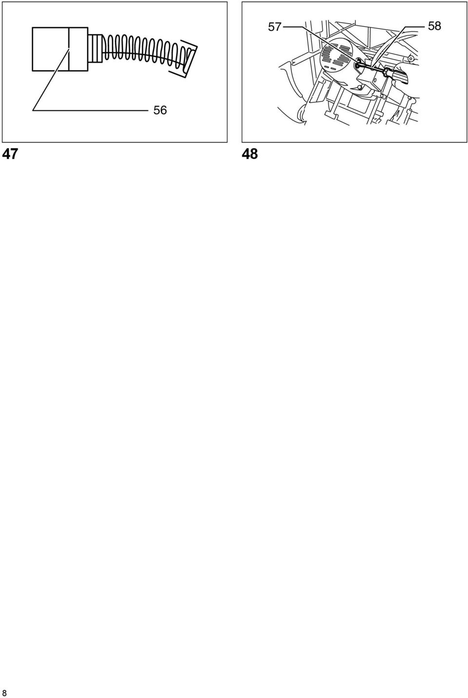
15 Lubrication To keep the table saw in tip-top running condition, and to assure maximum service life, oil or grease the moving parts and rotating parts from time to time. Lubrication places: Threaded shaft to elevate the blade Hinge to rotate the frame Elevation guide shafts on motor Gear to elevate the blade Guide rails for the rip fence Shaft of the sub table (R) locking levers Sliding part of the sub table (R) Replacing carbon brushes Remove and check the carbon brushes regularly. Replace when they wear down to the limit mark. Keep the carbon brushes clean and free to slip in the holders. Both carbon brushes should be replaced at the same time. Use only identical carbon brushes. (Fig. 47) Use a screwdriver to remove the brush holder caps. To replace the carbon brushes, remove the blade guard and blade and then loosen the lock lever, tilt the saw head and secure it at 45 bevel angle. Carefully lay the tool on itself backward. Then loosen the brush holder cap. Remove the worn carbon brushes, insert the new ones and secure the brush holder caps. (Fig. 48) To maintain product SAFETY and RELIABILITY, repairs, any other maintenance or adjustment should be performed by Makita Authorized Service Centers, always using Makita replacement parts. ACCESSORIES These accessories or attachments are recommended for use with your Makita tool specified in this manual. The use of any other accessories or attachments might present a risk of injury to persons. Only use accessory or attachment for its stated purpose. If you need any assistance for more details regarding these accessories, ask your local Makita service center. Table stand set (accessory) Refer to the instruction manual for table saw stand that is provided with the table saw stand as an optional accessory. Steel & Carbide-tipped saw blades Sub table (L) Sub table (back) Rip fence Miter gauge Offset wrench Wrench 19 Hex wrench 5 Joint (for connecting to dust collector) Auxiliary plate Stand set Sliding guide 15

16 NEDERLANDS 1. Diameter gat 8 mm 2. Sluitring 6 mm 3. Houtschroef nr. 10 minimale lengte 40 mm 4. Bout en moer 6 mm goed aandraaien 5. Verstekgeleider 6. Breedtegeleider 7. Draaihendel 8. Vergrendelhendel 9. Pijltje 10. Handwiel Stelschroef Stelschroef 13. Schakelaar 14. Hangslot 15. Hendel 16. Hulptafel (R) 17. Schaalplaat 18. Schroef 19. Hulptafel (achter) 20. Hulptafel (L) Verklaring van het onderdelenoverzicht 21. Versprongen steeksleutel 22. Zeskantmoer 23. Sleutel 24. Binnenflens 25. Ring 26. Zaagblad 27. Buitenflens 28. Beschermkap 29. Spouwmes 30. Montagegedeelte (steun) van beschermkap 31. Zaagblad 32. Deze twee spelingen moeten gelijk zijn. 33. Inbusbouten (B) 34. Zeskantbouten (A) 35. Haak 36. Knop 37. Geleiderail 38. Schaal 39. Inbusbouten 40. Geleidelijn 41. Schroeven 42. Bovenkant/onderkant zijaanzicht 43. Houtschroef 44. Vastlijmen 45. Houtschroeven nr. 10 (met voldoende lengte om het geleidebord halverwege binnen te dringen) 46. Duwstok 47. Hulpgeleider 48. Duwblok 49. AFKORTEN 50. HORIZONTAAL VERSTEKZAGEN 51. VERTICAAL VERSTEKZAGEN 52. SAMENGESTELD VERSTEKZAGEN (HORIZONTALE EN VERTICALE HOEKEN) 53. Plaatje 54. Schroef voor de hoekaanslag 55. Groef 56. Limietmarkering 57. Koolborsteldop 58. Schroevendraaier TECHNISCHE GEGEVENS Model 2704 (voor Europese landen) (voor niet-europese landen) Asgat 30 mm 25 mm Diameter zaagblad 260 mm 255 mm Max. zaag mm 91 mm dikte mm 63 mm Toerental onbelast (min -1 ) Tafelafmetingen (L x B) Afmetingen (L x B x H) met gemonteerde hulptafels niet uitgezet (665 mm mm) x (753 mm mm) met gemonteerde hulptafels (R) en (achter) 715 mm x 753 mm x 344 mm met gemonteerde hulptafels (R) en (achter) 567 mm x (753 mm mm) met gemonteerde hulptafel (R) 665 mm x 753 mm x 344 mm met gemonteerde hulptafel (R) Netto gewicht 36 kg 30 kg Veiligheidsklasse /II Als gevolg van ons doorlopende onderzoeks- en ontwikkelingsprogramma, zijn de technische gegevens van dit gereedschap onderhevig aan veranderingen zonder voorafgaande kennisgeving. Opmerking: De technische gegevens kunnen van land tot land verschillen. Symbolen De symbolen van het gereedschap worden hieronder weergegeven. Zorg ervoor dat u de betekenis ervan voor gebruik begrijpt.... Lees de gebruiksaanwijzing.... DUBBELE ISOLATIE... Draag een veiligheidsbril.... Houdt handen en vingers uit de buurt van het zaagblad. Gebruiksdoeleinden Het gereedschap is bedoeld om hout te zagen. Voeding Het gereedschap mag uitsluitend worden aangesloten op een voeding met dezelfde spanning als aangegeven op het identificatieplaatje en werkt alleen op enkele-fase wisselstroom. Het gereedschap is dubbel geïsoleerd volgens de Europese norm en mag derhalve ook op een niet-geaard stopcontact worden aangesloten. 38
 van beschermkap 31. Zaagblad 32. Deze twee spelingen moeten gelijk zijn. 33. Inbusbouten (B) 34. Zeskantbouten (A) 35. Haak 36. Knop 37. Geleiderail 38. Schaal 39.")
17 AANVULLENDE VEILIGHEIDSVOORSCHRIFTEN VOOR HET GEREEDSCHAP BEWAAR DEZE VOORSCHRIFTEN 1. Draag oogbescherming. 2. Gebruik het gereedschap niet in de buurt van ontvlambare vloeistoffen of gassen. 3. Gebruik het gereedschap NOOIT met een doorslijpschijf erop gemonteerd. 4. Controleer vóór het gebruik het zaagblad zorgvuldig op barsten of beschadiging. Vervang een gebarsten of beschadigd zaagblad meteen. 5. Gebruik alleen zaagbladen die aanbevolen worden door de fabrikant en die voldoen aan de norm EN847-1, en let erop dat het spouwmes niet dikker is dan de zaagbreedte van het zaagblad en niet dunner is dan het zaagblad zelf. 6. Gebruik altijd de accessoires die in deze gebruiksaanwijzing aanbevolen worden. Gebruik van ongeschikte accessoires, zoals slijpschijven, kan tot letsel leiden. 7. Kies voor het materiaal, dat u wilt bewerken, het geschikte zaagblad. 8. Zaagbladen van hooggelegeerd snelstaal (HSS) mogen niet worden gebruikt. 9. Zorg, om het geluidsniveau te verminderen, er altijd voor dat het zaagblad scherp en schoon is. 10. Gebruik een zaagblad dat op de juiste wijze geslepen is. Houd u aan de maximale snelheid aangegeven op het zaagblad. 11. Reinig de as, de flenzen (vooral het montagevlak) en de zeskantmoer voordat u het zaagblad monteert. Gebrekkige montage kan trilling/ schommeling of slippen van het zaagblad veroorzaken. 12. Gebruik de beschermkap en het spouwmes voor elk soort werk waarvoor deze kunnen worden gebruikt, inclusief alle doorzaagactiviteiten. Monteer altijd de beschermkap volgens de instructies beschreven in deze gebruiksaanwijzing. Doorzaagactiviteiten zijn activiteiten waarbij het zaagblad het werkstuk helemaal doorzaagt, zoals bij schulpen of afkorten. Gebruik het gereedschap NOOIT met een defecte beschermkap en maak de beschermkap nooit vast door middel van een touw, een koord e.d. Elke abnormale werking van de beschermkap moet onmiddellijk worden gerepareerd. 13. Monteer onmiddellijk weer de beschermkap en het spouwmes, na het voltooien van de activiteit waarvoor demontage van de beschermkap noodzakelijk was. 14. Zaag niet op metalen zoals spijkers en schroeven. Inspecteer het werkstuk en verwijder alle spijkers, schroeven en andere dingen die er niet thuis horen, voordat u met het zagen begint. 15. Verwijder sleutels, afgezaagde stukken e.d. van het tafelblad voordat u het gereedschap inschakelt. 16. Draag NOOIT handschoenen tijdens het bedienen van het gereedschap. 17. Houd uw handen uit de buurt van de looplijn van het zaagblad. 18. Sta NOOIT in het verlengde van de zaaglijn van het zaagblad, en laat niet toe dat iemand anders daar gaat staan. 19. Zorg ervoor dat het zaagblad het spouwmes of het werkstuk niet raakt voordat u het gereedschap hebt ingeschakeld. 20. Laat het gereedschap een tijdje draaien voordat u het werkstuk gaat zagen. Controleer op trillingen of schommelingen die op onjuiste montage of een slecht uitgebalanceerd zaagblad kunnen wijzen. 21. Het gereedschap mag niet gebruikt worden voor elke vorm van freeswerk. 22. Vervang de inzettafel als deze versleten is. 23. Verander NOOIT de instelling van het gereedschap als deze ingeschakeld is. Haal de stekker uit het stopcontact voordat u de instellingen verandert. 24. Gebruik indien nodig een duwstok. Een duwstok MOET worden gebruikt voor het schulpen van smalle werkstukken, zodat uw handen en vingers op veilige afstand van het zaagblad blijven. 25. Berg de duwstok altijd op als deze niet wordt gebruikt. 26. Schenk speciale aandacht aan de voorzorgsmaatregelen voor het voorkomen van TERUGSLAG. TERUGSLAG is een plotselinge reactie op een bekneld, vastgelopen of nietuitgelijnd zaagblad. TERUGSLAG leidt ertoe dat het werkstuk van het gereedschap wordt weggeslingerd in de richting van de gebruiker. TERUGSLAG KAN LEIDEN TOT ERNSTIG PERSOONLIJK LETSEL. Voorkom TERUGSLAG door de volgende voorzorgsmaatregelen in acht te nemen: Gebruik altijd een goed aangescherpt zaagblad. Houd de breedtegeleider evenwijdig met het zaagblad. Houd het spouwmes, de vingers voor terugslagbeveiliging en de beschermkap op hun plaats gemonteerd en zorg ervoor dat deze naar behoren werken. Laat het werkstuk niet los totdat u het helemaal voorbij het zaagblad hebt geduwd. Schulp geen werkstuk dat verbogen of kromgetrokken is of geen rechte rand heeft die langs de geleider kan worden geplaatst. 27. Zaag nooit uit de vrije hand. "Uit de vrije hand" betekent dat in plaats van de verstekgeleider of de breedtegeleider u uw handen gebruikt om het werkstuk te ondersteunen of te geleiden. 28. Reik NOOIT rond of over het zaagblad. Reik NOOIT naar een werkstuk voordat het zaagblad volledig tot stilstand is gekomen. 29. Vermijd bruusk en snel aanvoeren van het werkstuk. Voer harde werkstukken zo langzaam mogelijk aan. Buig of verdraai het werkstuk niet tijdens het aanvoeren. Als het zaagblad in het werkstuk vast blijft zitten of blokkeert, moet u het gereedschap onmiddellijk uitschakelen. Haal de stekker uit het stopcontact. Maak het werkstuk vrij. 39

18 30. Verwijder NOOIT zaagafval dicht bij het zaagblad en raak de beschermkap nooit aan terwijl het zaagblad draait. 31. Verwijder elk loszittende houtknoest uit het werkstuk voordat u het begint te zagen. 32. Misbruik het netsnoer niet. Trek nooit aan het netsnoer om de aansluiting op het stopcontact te verbreken. Houd het netsnoer uit de buurt van hitte, olie, water en scherpe randen. 33. Stof dat tijdens de werkzaamheden vrijkomt, kan chemische bestanddelen bevatten die kanker, geboortedefecten of andere voortplantingsschade kan (kunnen) verwekken. Enkele voorbeelden van deze chemische stoffen zijn: - lood van loodhoudende verfstoffen en - arsenicum en chroom van chemisch behandeld hout. - Uw risico van deze blootstellingen varieert en hangt af van het feit hoe vaak u dit soort bewerkingen uitvoert. Om blootstelling aan deze chemische bestanddelen te verminderen: moeten de werkzaamheden uitgevoerd worden in een goed geventileerde werkomgeving en gebruikmakend van goedgekeurd beschermende hulpmiddelen, zoals stofmaskers die ontworpen zijn om microscopisch kleine deeltjes te kunnen filteren. 34. Sluit het gereedschap aan op een stofafzuig- en stofopvanginrichting tijdens het zagen. 35. De beschermkap kan omhoog gezet worden om het werkstuk in positie te brengen en om het schoonmaken te vereenvoudigen. Zorg er altijd voor dat de beschermkap zich in de benedenpositie vlak op de tafelcirkelzaag bevindt, voordat u de stekker in het stopcontact steekt. BEWAAR DEZE VOORSCHRIFTEN OPSTELLEN De tafelcirkelzaag opstellen (zie afb. 1 t/m 3) Stel de tafelcirkelzaag op een goed verlichte en horizontale plaats op waar u goede steun voor de voeten hebt en uw evenwicht niet kunt verliezen. Zorg ervoor dat er rond de tafelcirkelzaag voldoende ruimte is om uw werkstukken gemakkelijk te kunnen hanteren. De tafelcirkelzaag moet op een werkbank of speciale standaard worden vastgezet door middel van vier schroeven of bouten die u door de gaten in het voetstuk van de tafelcirkelzaag steekt. Wanneer u de tafelcirkelzaag op een werkbank vastzet, moet het bovenblad van de werkbank voorzien zijn van een opening die even groot is als de opening in het voetstuk van de tafelcirkelzaag, zodat het zaagsel erdoor kan vallen. Als de tafelcirkelzaag tijdens het gebruik neigt om te kantelen of gauw verschuift of beweegt, moet een werkbank of een speciale standaard voor de tafelcirkelzaag op de vloer worden bevestigd. Bergruimte voor accessoires (zie afb. 4 en 5) Er is bergruimte voor de verstekgeleider, het zaagblad en de sleutels aan de linkerzijde van de gereedschapvoet, en voor de breedtegeleider aan de rechterzijde van de gereedschapvoet. De beschermkap kan worden verwijderd en daarna rechts op de achterkant worden opgeborgen. BESCHRIJVING VAN DE FUNCTIES Controleer altijd of het gereedschap is uitgeschakeld en de stekker uit het stopcontact is getrokken alvorens de functies van het gereedschap te controleren of af te stellen. Instellen van de zaagdiepte (zie afb. 6) De zaagdiepte kan worden ingesteld door de hendel linksom of rechtsom te draaien. Draai de hendel rechtsom om het zaagblad hoger te zetten, of linksom om het zaagblad lager te zetten. OPMERKING: Om bij het zagen van dun materiaal een schonere zaagsnede te verkrijgen moet u een geringe zaagdiepte gebruiken. Instellen van de verstekhoek (zie afb. 7) Draai de vergrendelhendel los en draai het handwiel om de gewenste hoek (0 45 ) te krijgen. De verstekhoek wordt door het pijltje aangegeven. Nadat de gewenste hoek is ingesteld, draait u de vergrendelhendel weer vast om de instelling te vergrendelen. Zorg dat de vergrendelhendel, na instelling van de verticale verstekhoek, stevig vastgezet is. De hoekaanslagen afstellen Het gereedschap is voorzien van aanslagen op 90 en 45 ten opzichte van het tafelblad. Ga als volgt te werk om de hoekaanslagen te controleren en zonodig af te stellen (zie afb. 8): Verplaats het handwiel zo ver mogelijk door eraan te draaien. Plaats de driehoekige liniaal op de tafel en controleer of het zaagblad onder een hoek van 90 of 45 staat ten opzichte van het tafelblad. Als de hoek van het zaagblad is zoals in afb. A, moet u de stelschroeven rechtsom draaien. Als de hoek is zoals in afb. B, moet u de stelschroeven linksom draaien om de hoekaanslagen af te stellen (zie afb. 9). Nadat de hoekaanslagen zijn afgesteld, moet u het zaagblad op 90 ten opzichte van het tafelblad zetten. Stel daarna de positie van het pijltje af zodat zijn rechter uiteinde overeenkomt met de 0 schaalverdeling (zie afb. 10). 40
 verwekken.")
19 Werking van de aan/uit-schakelaar Voor de hefboomschakelaar Zorg er voor dat het gereedschap is uitgeschakeld, voordat u de stekker in het stopcontact steekt. Om het gereedschap in te schakelen, duwt de hefboomschakelaar omhoog. Om het gereedschap te stoppen, duwt u de hefboomschakelaar omlaag (zie afb. 11). De hefboom kan op slot gedaan worden door een met behulp van een hangslot door sluithaak aan de linkerkant (zie afb. 12). Voor de wipschakelaar (zie afb. 13) Zorg ervoor het gereedschap in en uit te schakelen, voordat u het bedient. Om het gereedschap te starten, drukt u de "ON ( I ) -knop in. Om het gereedschap te stoppen, drukt u de "OFF ( O ) - knop in. Hulptafel (R) Deze machine is voorzien van een hulptafel (R) aan de rechterkant van het hoofdtafel. Om gebruik te maken van de hulptafel (R), moet u beide hendels aan de rechter voorzijde omhoog tillen, de tafel (R) volledig uittrekken en daarna de hendels naar beneden brengen om het vast te zetten. (zie afb. 14 en& 15). Breng bij gebruik van de hulptafel (R) de schaalplaat, na het losmaken van een schroef met een schroevendraaier, aan op de hulptafel zodat deze in lijn ligt met de schaalplaat op de hoofdtafel (zie afb. 16). Hulptafel (achter) (zie afb. 17) Om de hulptafel (achter) gebruiksklaar te maken, draait u de schroef aan de linkeronderzijde van de hoofdtafel los en trekt u de tafel eruit naar achteren tot de gewenste afstand. Draai op de gewenste afstand de schroef goed vast. OPMERKING: Bij gelijktijdig gebruik van de hulptafel (achter) en de breedtegeleider, moet de hulptafel (achter) meer dan 50 mm uitgetrokken worden, zodat deze niet de bovenkant van de breedtegeleider raakt. Hulptafel (L) (los verkrijgbaar) (zie afb. 18) De hulptafel (L) (los verkrijgbaar) kan gemonteerd worden aan de linkerkant van de tafelcirkelzaag om zodoende een bredere werkruimte te verkrijgen. ONDERDELEN AANBRENGEN/ VERWIJDEREN Controleer altijd of het gereedschap is uitgeschakeld en de stekker uit het stopcontact is getrokken alvorens enige werk aan het gereedschap uit te voeren. Bij de verscheping van het gereedschap uit de fabriek, zijn het zaagblad en de beschermkap niet op het gereedschap gemonteerd. Monteer deze als volgt: Het zaagblad monteren en verwijderen Controleer altijd of het gereedschap is uitgeschakeld en de stekker uit het stopcontact is getrokken alvorens het zaagblad te monteren of verwijderen. Gebruik uitsluitend de bijgeleverde Makita-dopsleutel bij het monteren of verwijderen van het zaagblad. Als u dit nalaat, loopt u het risico dat de zeskantbout te vast of onvoldoende vast aangedraaid wordt. Hierdoor kan letsel worden veroorzaakt. Gebruik het hieronder gespecificeerde zaagblad. Gebruik geen zaagbladen die niet voldoen aan de specificaties in deze gebruiksaanwijzing. Voor model Max. diameter Min. diameter mm 220 mm Zaagbladdikte 1,4 mm 1,8 mm Zaagsnede 2 mm of meer Controleer vóór montage de diameter van het asgat van het zaagblad. Gebruik altijd de ring die bestemd is voor het asgat van het zaagblad dat u gaat monteren. Verwijder het inzetstuk van de tafelcirkelzaag. Zet de versprongen steeksleutel op de buitenflens en draai de zeskantmoer linksom los met de rechte steeksleutel. Verwijder dan de buitenflens (zie afb. 19). Monteer de binnenflens, ring, zaagblad, buitenflens en zeskantmoer op de as, en zorg ervoor dat de tanden van het zaagblad aan de voorkant van de tafelcirkelzaag naar beneden gericht zijn. Monteer de zeskantmoer altijd met zijn uitgeholde zijde naar de buitenflens gekeerd (zie afb. 20). Voor alle niet-europese landen De zilverkleurige ring, met een buitendiameter van 25,4 mm, is door de fabrikant op de as aangebracht. De zwarte ring, met een buitendiameter van 25 mm, is meegeleverd als standaard toebehoren. Voordat het zaagblad op de as wordt gemonteerd, moet u ervoor zorgen, dat de juiste ring, passend voor het asgat van het zaagblad, aangebracht is op de as. Voor Europese landen De ring, met een buitendiameter van 30 mm, is door de fabrikant aangebracht tussen de binnenste en buitenste flens. Houd het flensoppervlak vrij van vuil en ander materiaal dat er zich op hecht omdat het anders doorslaan van het zaagblad kan veroorzaken. Zorg ervoor dat het zaagblad zodanig gemonteerd wordt dat de zaagtanden in de lijn van de zaag (draai)-richting staan. Om het zaagblad vast te zetten, moet u de buitenflens met de versprongen steeksleutel vasthouden en de zeskantmoer met steeksleutel rechtsom vastdraaien. DRAAI DE ZESKANTMOER GOED VAST (zie afb. 21). Zorg ervoor dat de steeksleutel goed om de zeskantmoer zit. Als u grip verliest, kan de steeksleutel losschieten van de zeskantmoer en loopt u het risico dat uw hand in aanraking komt met de zaagtanden. 41
 Zorg ervoor het gereedschap in en uit te schakelen, voordat u het bedient. Om het gereedschap te starten, drukt u de \"ON ( I ) -knop in.")
20 De beschermkap monteren (zie afb. 22 en 23) Voordat u de beschermkap monteert, moet u de zaagdiepte in de maximale stand (hoogste stand) zetten. Voor een type beschermkap bestemd voor niet- Europese landen Verwijder de middelste afdekplaat. Steek de spouwmes in het montagegedeelte (steun) van de zaagbladbeschermkap. Draai de zeskantbouten (A) vast met de bijgeleverde steeksleutel. Voor een type beschermkap bestemd voor Europese landen Verwijder de middelste afdekplaat. Steek de spouwmes in het montagegedeelte (steun) van de zaagbladbeschermkap. Draai de zeskantbouten (A) vast met de bijgeleverde steeksleutel. Plaats de beschermkap in de groef op het spouwmes. Zet de beschermkap vast door de hendel op de beschermkap te kantelen (zie afb. 24 en 25). De montagepositie van het spouwmes is in de fabriek afgesteld, zodat het zaagblad en het spouwmes normaal in een rechte lijn zullen staan. Indien dit niet het geval is, moet u de inbusbouten (B) losdraaien en het montagegedeelte (steun) van de beschermkap afstellen zodat het spouwmes in een rechte lijn achter het zaagblad komt te staan. Draai daarna de inbusbouten (B) weer vast om de steun vast te zetten (zie afb. 26). Als het zaagblad en het spouwmes niet goed uitgelijnd zijn, kunnen deze tijdens het gebruik gaan knellen, wat gevaarlijk is. Let daarom goed op de juiste uitlijning. Bij gebruik van het gereedschap zonder een goed uitgelijnd spouwmes, kunt u ernstig persoonlijk letsel oplopen. Verander NOOIT de instelling van het gereedschap als deze ingeschakeld is. Haal de stekker uit het stopcontact voordat u de instellingen verandert. De speling tussen het spouwmes en de tanden van het zaagblad moet 4 tot 5 mm zijn. Stel het spouwmes dienovereenkomstig af en draai de zeskante bouten (A) goed vast. Monteer het inzetstuk op het tafelcirkelzaag en controleer vervolgens of de beschermkap soepel werkt (zie afb. 27). Monteren en afstellen van de breedtegeleider 1) Plaats de haak aan de bovenkant van de breedtegeleider achter in de geleiderail van de hoofdtafel of de hulptafel (R) en monteer en duw de breedtegeleider naar voren, dusdanig dat de geleiderhouder vastgezet wordt in de dichtstbijzijnde geleiderail (zie afb. 28). Kantel de knop op de geleiderhouder halverwege om de breedtegeleider zijwaarts in de geleiderail te schuiven. Om de breedtegeleider vast te zetten moet u de knop op de geleiderhouder volledig kantelen. 2) Om de breedtegeleider zijwaarts in de geleiderail te schuiven, kantelt u de knop op de geleiderhouder helemaal terug zonder aan de hendel op de knop te trekken. 3) Om deze te verwijderen, moet u aan de hendel op de knop trekken en de knop met uitgetrokken hendel naar voren kantelen. Om te controleren of de breedtegeleider parallel is met het zaagblad, zet u de breedtegeleider vast op 2 tot 3 mm van het zaagblad. Breng het zaagblad tot in zijn hoogste positie omhoog. Markeer een van de zaagbladtanden met een tekenkrijt. Meet afstanden (A) en (B) tussen de breedtegeleider en het zaagblad. Gebruik voor beide metingen de tand die met het tekenkrijt werd gemarkeerd. Deze twee gemeten afstanden moeten exact hetzelfde zijn. Ga als volgt te werk als de breedtegeleider niet parallel is met het zaagblad (zie afb. 29 en 31): 1. Zet het spouwmes in de schuifstand. 2. Draai de twee inbusbouten op de breedtegeleider los met de bijgeleverde inbussleutel. 3. Stel de breedtegeleider af totdat deze parallel is met het zaagblad. 4. Breng de knop op de breedtegeleider naar u omlaag. 5. Draai de twee inbusbouten op de breedtegeleider vast. Zorg ervoor dat de breedtegeleider evenwijdig is met het zaagblad, omdat er anders gevaar bestaat voor gevaarlijke terugslag. Plaats de breedtegeleider vlak tegen de zijkant van het zaagblad. Zorg ervoor dat het pijltje op de geleiderhouder naar de 0 schaalverdeling wijst. Als het pijltje niet naar de 0 schaalverdeling wijst, draai dan de schroef op de schaalplaat los en stel de schaalplaat af (zie afb. 32). Aansluiten op een stofzuiger (zie afb. 33) Door een Makita-stofzuiger of -stofvanger op de tafelcirkelzaag aan te sluiten, kunt u nog schoner werken. BEDIENING Gebruik altijd hulpmiddelen zoals duwstokken en duwblokken wanneer er gevaar bestaat dat uw handen of vingers dichtbij het zaagblad komen. Houd het werkstuk altijd goed vast op de tafelblad met behulp van breedtegeleider en verstekgeleider. Buig of verdraai het werkstuk niet tijdens het aanvoeren. Als het werkstuk gebogen of verdraaid wordt, kan gevaarlijke terugslag optreden. Probeer NOOIT het werkstuk terug te nemen terwijl de zaag nog draait. Wanneer u het werkstuk wilt terugnemen voordat het volledig is gezaagd, moet u eerst het gereedschap uitschakelen terwijl u het werkstuk stevig vasthoudt. Wacht totdat het zaagblad volledig tot stilstand is gekomen en verwijder dan het werkstuk. Als u dat niet doet, kan gevaarlijke terugslag worden veroorzaakt Verwijder NOOIT afgezaagd materiaal terwijl het zaagblad nog draait. Breng uw handen of vingers NOOIT in de zaaglijn van het zaagblad. Wees vooral voorzichtig tijdens verstekzagen. Zet de breedtegeleider altijd goed vast om gevaarlijke terugslag te voorkomen. Gebruik altijd hulpmiddelen zoals duwstokken en duwblokken wanneer u kleine of smalle werkstukken 42
 van de zaagbladbeschermkap. Draai de zeskantbouten (A) vast met de bijgeleverde steeksleutel. Plaats de beschermkap in de groef op het spouwmes.")
21 zaagt of wanneer het zaagblad tijdens het zagen niet zichtbaar is. Hulpmiddelen Duwstokken, duwblokken of een extra hulpgeleider zijn voorbeelden van hulpmiddelen. Gebruik ze om veilig zuivere zaagsneden te maken zonder dat de bedienaar met enig deel van zijn lichaam in aanraking komt met het zaagblad. Duwblok (zie afb. 34) Gebruik een stuk multiplex van 19 mm dik. De handgreep moet in het midden van het stuk multiplex zitten. Bevestig met lijm en houtschroeven zoals afgebeeld. Het kleine stuk hout (9,5 mm x 8 mm x 50 mm) moet altijd aan het triplex gelijmd worden om te voorkomen dat het zaagblad stomp wordt als de bediener per ongeluk in het duwblok zaagt. (Gebruik nooit spijkers in het duwblok.) Extra hulpgeleider (zie afb. 35) Maak een hulpgeleider van stukken multiplex van 9,5 mm en 19 mm dik. Houten beschermstuk (breedtegeleider) (zie afb. 36). Een houten beschermstuk wordt aangebracht op de breedtegeleider en wordt toegepast voor zaagwerkzaamheden waarbij het zaagblad dicht bij de breedtegeleider komt. Het houten beschermstuk van de breedtegeleider moet even groot zijn als de breedtegeleider. Zorg ervoor dat de onderzijde van het beschermstuk vlak op het tafeloppervlak rust. Schulpen Voor schulpen moet de verstekgeleider vanaf de tafelcirkelzaag worden verwijderd. Wanneer u lange of brede werkstukken zaagt, moet u altijd achter de tafelcirkelzaag een geschikte steun plaatsen. Zorg ervoor dat een lange plank NIET op de tafelblad kan bewegen of schuiven. Hierdoor kan het zaagblad vastgeklemd raken en de mogelijkheid op terugslag en persoonlijk letsel vergroten. De steun moet even hoog zijn als het tafelblad. 1. Stel de zaagdiepte iets groter in dan de dikte van het werkstuk (zie afb. 37). 2. Plaats de breedtegeleider op de gewenste breedte van de schulp en klem deze stevig op zijn plaats door de handgreep te kantelen. Zorg voordat u gaat schulpzagen, dat het achterste einde van de breedtegeleider goed vastgezet is. Als deze niet vast genoeg zit moet u de aanwijzingen in het hoofdstuk De breedtegeleider monteren en afstellen opvolgen. 3. Schakel het gereedschap in en voer het werkstuk langzaam langs de hulpgeleider aan. (1) Bij een schulpbreedte groter dan 150 mm, gebruikt u voorzichtig uw rechterhand om het werkstuk in te voeren. Gebruik uw linkerhand om het werkstuk op zijn plaats tegen de breedtegeleider te houden )zie afb. 38). (2) Bij een schulpbreedte groter dan 65 mm, gebruikt u voorzichtig uw rechterhand om het werkstuk in te voeren. (3) Bij een schulpbreedte kleiner dan 65 mm kan de duwstok niet gebruikt worden omdat de duwstok Afkorten dan in aanraking komt met het zaagblad. Gebruik een hulpgeleider en een duwblok. Bevestig de hulpgeleider aan de schulpgeleider met twee lijmtangen (zie afb. 40). Voer het werkstuk met de hand in totdat het eindstuk circa 25 mm verwijderd is van de voorzijde van het tafelblad. Ga door met het invoeren met behulp van een duwblok op de hulpgeleider totdat de zaagsnede voltooid is (zie afb. 41). Voor afkorten moet de breedtegeleider vanaf de tafelcirkelzaag worden verwijderd. Wanneer u lange of brede werkstukken zaagt, moet u altijd aan beide zijkanten van de tafelcirkelzaag een geschikte steun plaatsen. De steun moet even hoog zijn als het tafelblad. Houd handen altijd weg van de zaaglijn van het zaagblad. Verstekgeleider (zie afb. 42) Gebruik de verstekgeleider bij de 4 manieren van zagen, zoals weergegeven in de afbeelding. Zet de knop op de verstekgeleider stevig vast. Voorkom, door goede klemvoorzieningen, dat het werkstuk en de aanslag kan wegkruipen, in het bijzonder bij het zagen onder een hoek. U mag NOOIT het deel van het werkstuk dat u wilt afzagen vasthouden of beetpakken. Stel de afstand tussen de verstekgeleider en de zaagtafel altijd zodanig in dat deze niet groter is dan 15 mm. Aanslagen van de verstekgeleider (zie afb. 43) Om de verstekhoeken snel in te kunnen stellen is het gereedschap voorzien van aanslagen bij linker- en rechterverstekhoeken van 90 en 45. Draai de knop op de verstekgeleider los en stel in op de gewenste hoek. Breng het plaatje op de verstekgeleider omhoog voor het instellen van elke andere verstekhoek. Zwenk de verstekgeleider in de gewenste verstekhoek. Breng het plaatje op de verstekgeleider in de oorspronkelijke positie terug en draai de knop rechtsom stevig vast. Gebruik van de verstekgeleider (zie afb. 44) Schuif de verstekgeleider in de brede groeven van het tafelblad. Draai de knop op de geleider los en stel in op de gewenste hoek (0 tot 60 ). Plaats de achterzijde van het werkstuk vlak tegen de geleider en beweeg dit langzaam naar voren in de richting van het zaagblad. Extra houten hulpgeleider (voor verstekgeleider) (zie afb. 45) Om te voorkomen dat een lange plank gaat slingeren, moet u een extra houten hulpgeleider aan de verstekgeleider bevestigen. Bevestig deze met bouten en moeren door vooraf geboorde gaten zonder dat ze uit het hout steken. 43
2000 Volkswagen Passat GLS
 REAR DOOR WINDOW Rear door window, assembly overview Fig. 304: Exploded View Of Rear Door Window 1 - Door Removing and installing: --> Rear door, removing and installing 2 - Spring nut Qty 2 3 - Screw
Flybye. Ernst Koning, Montagehandleiding / Instruction manual
 Flybye Ernst Koning, 2018 Montagehandleiding / Instruction manual GELEVERD MATERIAAL / MATERIALS SUPPLIED A. B. C. D. E. F. G. A. B. C. D. E. F. G. H. H. lichtbuis / lighting tube plafondkap / ceiling
Rhythm of Light. Susanne de Graef, Montagehandleiding / Instruction manual
 Rhythm of Light Susanne de Graef, 2016 Montagehandleiding / Instruction manual GELEVERD MATERIAAL / SUPPLIED MATERIAL B. C. D. A. E. F. A. B. C. D. E. F. armatuur / fixture fitting lange staalkabels (3)
2006 Volkswagen Jetta TDI
 Door handle and door lock, assembly overview The illustration shows the left side. The right side is derived accordingly from this. Fig. 99: Door Handle And Door Lock, Assembly Overview 1 - Cable For disengaging
Dagelijkse checklist Daily checklist
 Dagelijkse checklist Daily checklist Sluiting met snelspanner Verstelbare hoofdsteun Verstelbare en aanpasbare riem Verstelbare voetsteunen Verstelbare riemen van de voetsteun Quick release locked Head
OUTDOOR HD BULLET IP CAMERA PRODUCT MANUAL
 OUTDOOR HD BULLET IP CAMERA PRODUCT MANUAL GB - NL GB PARTS & FUNCTIONS 1. 7. ---- 3. ---- 4. ---------- 6. 5. 2. ---- 1. Outdoor IP camera unit 2. Antenna 3. Mounting bracket 4. Network connection 5.
MONTAGE INSTRUCTIE ASSEMBLY INSTRUCTION
 MONTAGE INSTRUCTIE ASSEMBLY INSTRUCTION - 1. Waterpas stellen. De groef aan de zijkant van de beschermdeksel moet gelijk staan met de deellijn van het inbouw box. 2. Zet de inbouw box vast in de muur.
NEDERLANDS. Plaatselijke telefoonnummers voor de klantendienst kunt u vinden op: G-01 rev.
 For the latest User Installation Guide please visit: www.ergotron.com User's Guide - English Guía del usuario - Español Manuel de l utilisateur - Français Gebruikersgids - Deutsch Benutzerhandbuch - Nederlands
OUTDOOR HD DOME IP CAMERA PRODUCT MANUAL GB - NL
 OUTDOOR HD DOME IP CAMERA PRODUCT MANUAL GB - NL GB PARTS & FUNCTIONS 2. ---- 1. ---- 3. ---- 7. ---------- 5. 4. 6. 1. Outdoor IP camera unit 2. Antenna 3. Mounting bracket 4. Network connection 5. Power
Συρόμενο σύνθετο φαλτσοπρίονο Οδηγίες χρήσης
 GB Slide Compound Miter Saw Instruction manual F Scie à onglet radiale Manuel d instructions D Kapp- und Gehrungssäge Betriebsanleitung I Troncatrice radiale per legno Istruzioni per l uso NL Schuifbare
Montagehandleiding: doucheset
 Montagehandleiding: doucheset Installation manual: showerset 0 6 5 7 8 9 0 8 9 7 5 6 Controleer voor installatie of alle onderdelen aanwezig zijn. Check if all parts are present before installation. 5
INSTALATIEGIDS VIDEOWALL
 INSTALATIEGIDS VIDEO 1. Bereken de hoogte van de rails door te meten hoeveel lager het onderste scherm zal uitkomen. Je kan dit meten aan de achterkant van de display, waar de beugels op gemonteerd zijn.
Limpid Light. design Esther Jongsma & Sam van Gurp, Montagehandleiding / Assembly Instructions
 Limpid Light design Esther Jongsma & Sam van Gurp, 05 Montagehandleiding / Assembly Instructions GELEVERD MATERIAAL / SUPPLIED MATERIAL A. A. B. B. C. D. E. F. G. G. H. I. J. K. / / ophanging / suspension:
EU Declaration of Conformity and safety instructions EU Conformiteitsverklaring en veiligheidsinstructies ISC 230B
 EU Declaration of Conformity and safety instructions EU Conformiteitsverklaring en veiligheidsinstructies ISC 230B Explosion safety instructions (Ex) (EN) ISC230B is approved for use outside the explosion-hazardous
Kies uit setje A of B voor deze bakfiets Choose between set A or B for this transportbike
 Kies uit setje A of B voor deze bakfiets Choose between set A or B for this transportbike A A Selecteer op bestelformulier: Houtenbak gat 5 punts bevestiging Set A: standaard setje voor bevestiging icm
EU Declaration of Conformity and safety instructions EU Conformiteitsverklaring en veiligheidsinstructies
 EU Declaration of Conformity and safety instructions EU Conformiteitsverklaring en veiligheidsinstructies Battery operated UNICOM 300 N51 UNICOM 300 met batterijvoeding N51 Explosion safety instructions
FSW-VW-2X2 FSW-VW. Handleiding / Manual
 FSW-VW-2X2 FSW-VW Handleiding / Manual Rev. 1.0 17-03-2014 I Pakketinhoud / Content Accessoires Benodigde gereedschappen / Required Tools Montage / Assembling Onderhoud / Maintenance Veel Gestelde Vragen
GB Cordless Circular Saw Instruction Manual Scie circulaire sans fil Manuel d instructions Akku-Handkreissäge Betriebsanleitung
 GB Cordless Circular Saw Instruction Manual F Scie circulaire sans fil Manuel d instructions D Akku-Handkreissäge Betriebsanleitung I Sega circolare a batteria Istruzioni per l uso NL Accu cirkelzaag Gebruiksaanwijzing
ANT S KINGDOM Here is some advice for setting up your Master Ant Farm!
 ANT S KINGDOM Master NL EN Instructies Mierenboerderij Master Bedankt voor je bestelling van de Mierenboerderij Master. De beste keus! Installatie NL Naast de informatie die te lezen is in ons boekje
1/8 ATLAS Atlas cabinet cabinet 1 7
 TLS cabinet / / / 0 D E F G H / L x Lx x L / x x D E Dx Ex / x x x x x x Fx x Hx Gx Fx Fx Fx Fx G H G H H G 0 0 0 0 0 / L / 0 NL: Deze kast bevat twee gaten aan de achterkant om aan de wand te kunnen bevestigen.
Dustless Cutter Instruction Manual Scie Diamanté Manuel d Instructions Diamantschneider Betriebsanleitung
 GB Dustless Cutter Instruction Manual F Scie Diamanté Manuel d Instructions D Diamantschneider Betriebsanleitung I Troncatrice con Aspirapolvere Istruzioni d Uso NL Diamant zaag droog Gebruiksaanwijzing
Mounting ceiling & wall
 5 / profile 34 bending radius R 15*) (1015) R 20 (1015) R 30 (1015) R>80 (1018) filler position profile 26 bending radius filler position R 15*) (1015) R 25 (1015) R>100 (1018) 28 15 405 gr/m 522 gr/m
Function checklist for the ML-350 or XL-350 with a print set. Missing loop.
 Function checklist for the ML-350 or XL-350 with a 260217 print set. Below mentioned check-point should resolve function problems of the lift systems. Missing loop. When a lift is connected to an external
GB Blower Instruction Manual Aspirateur Manuel d instructions Gebläse Betriebsanleitung
 GB Blower Instruction Manual F Aspirateur Manuel d instructions D Gebläse Betriebsanleitung I Soffiatrice-Aspiratore Istruzioni per l uso NL Blazer Gebruiksaanwijzing E Sopladora Aspiradora Manual de instrucciones
PIR DC-SWITCH. DC Passive infra-red Detector. Model No. PDS-10 GEBRUIKSAANWIJZING/INSTRUCTION MANUAL
 PIR DC-SWITCH DC Passive infra-red Detector Model No. PDS-10 GEBRUIKSAANWIJZING/INSTRUCTION MANUAL Please read this manual before operating your DETECTOR PIR DC-Switch (PDS-10) De PDS-10 is een beweging
Verstekzaagmachine Elu/DeWALT 230 V
 Verstekzaagmachine Elu/DeWALT 230 V Code: 700002 Veiligheidssymbolen: Fabricaat/merk: Type: Elu/DeWALT TGS 3 / DW 743 (N) Toepassing Zagen van hout, aluminium en kunststof. Veiligheidsvoorschriften Lees
Exalto wiper motor / wissermotor
 Exalto wiper motor / wissermotor Type: 215BD Cat. nos. 2151225/50/75 (12V) / 2152425/50/75 (24V) Quality Marine Equipment ! Contents 1 Dimensions and electrical scheme... 3 2 Adjusting the wiper arc....
Quick start guide. Powerbank MI Mah. Follow Fast All rights reserved. Page 1
 Quick start guide Powerbank MI 16.000 Mah Follow Fast 2016 - All rights reserved. Page 1 ENGLISH The Mi 16000 Power Bank is a very good backup option for those on the move. It can keep you going for days
CHROMA STANDAARDREEKS
 CHROMA STANDAARDREEKS Chroma-onderzoeken Een chroma geeft een beeld over de kwaliteit van bijvoorbeeld een bodem of compost. Een chroma bestaat uit 4 zones. Uit elke zone is een bepaald kwaliteitsaspect
HANDLEIDING Te chno Life Pla tinum
 HANDLEIDING Te chno Life Pla tinum 1 Onde rde le n ove rzicht. 3 Onde rde le nlijs t. NR. Naam e n Spe cificatie Aantal. NR. Naam e n Spe cificatie Aantal. 1 Hoofdframe 1 39 Plastic bus 6 2 Gewichtsgeleiders
Quality requirements concerning the packaging of oak lumber of Houthandel Wijers vof (09.09.14)
") Quality requirements concerning the packaging of oak lumber of (09.09.14) Content: 1. Requirements on sticks 2. Requirements on placing sticks 3. Requirements on construction pallets 4. Stick length and
Quality requirements concerning the packaging of oak lumber of (09.09.14) Content: 1. Requirements on sticks 2. Requirements on placing sticks 3. Requirements on construction pallets 4. Stick length and
Zone 1 and zone 2 Zone 21 and zone 22
 s en contactdozen s and sockets Productoverzicht Product overview Omschrijving: Index Elektro produceert een volledige lijn explosieveilige stekkers en contactdozen onder eigen certificaat. Deze worden
The upside down Louisa tutorial by Dorothée: Noortjeprullemie.blogspot.be Written for Compagnie M.: m.com
 The upside down Louisa tutorial by Dorothée: Noortjeprullemie.blogspot.be Written for Compagnie M.: www.compagnie- m.com Dorothée heeft een unieke Compagnie M. hack gemaakt: de Louisa op zijn kop. Als
INSTALLATION INSTRUCTION
 TV MOUNT INSTALLATION INSTRUCTION MODEL:HA051 HA051-T1 HA051-T6 Max VESA: 200 X 200 mm/8x8" Please read this instruction carefully before installation. Fits for most 14-32 inches Plasma, LCD and LED TVs.
!!!! Wild!Peacock!Omslagdoek!! Vertaling!door!Eerlijke!Wol.!! Het!garen!voor!dit!patroon!is!te!verkrijgen!op! Benodigdheden:!!
 WildPeacockOmslagdoek VertalingdoorEerlijkeWol. Hetgarenvoorditpatroonisteverkrijgenopwww.eerlijkewol.nl Benodigdheden: 4strengenWildPeacockRecycledSilkYarn rondbreinaaldnr8(jekuntnatuurlijkookgewonebreinaaldengebruiken,maar
7 Piece Fillet Weld Set
 7 Piece Fillet Weld Set Checking Fillet Throat Size Checking Fillet Leg Size Bridge Cam Gauge The following measurements are possible either in inches or millimeters Angle of preparation, 0º to 60º Excess
Smeertechniek Rotterdam Cairostraat 74 3047 BC Rotterdam Tel.: 010 466 62 55 Fax 010 466 66 55 Internet: www.smeertechniek.
 DEZE KOPPELINGEN WORDEN GEBRUIKT IN OLIE- EN VETSMEERSYSTEMEN IN PLAATS VAN DE SNIJRINGKOPPELINGEN ( SNIJRING & DRUKMOER ) KOPPELEN EN ONTKOPPELEN VAN DE LEIDING KAN HERHAALD WORDEN ZONDER BESCHADIGING
L.Net s88sd16-n aansluitingen en programmering.
 De L.Net s88sd16-n wordt via één van de L.Net aansluitingen aangesloten op de LocoNet aansluiting van de centrale, bij een Intellibox of Twin-Center is dat de LocoNet-T aansluiting. L.Net s88sd16-n aansluitingen
FRAME [UPRIGHT MODEL] / [DEPTH] / [HEIGHT] / [FINISH] TYPE OF BASEPLATE P Base plate BP80 / E alternatives: ZINC finish in all cases
![FRAME [UPRIGHT MODEL] / [DEPTH] / [HEIGHT] / [FINISH] TYPE OF BASEPLATE P Base plate BP80 / E alternatives: ZINC finish in all cases](/thumbs/60/44127117.jpg "FRAME [UPRIGHT MODEL] / [DEPTH] / [HEIGHT] / [FINISH] TYPE OF BASEPLATE P Base plate BP80 / E alternatives: ZINC finish in all cases") FRAME XS UPRIGHT BASE PLATE UPRIGHT HORIZONTAL PROFILE DIAGONAL PROFILE DESCRIPTION A vertical structure consisting of 2 uprights, joined by a system of bracing profiles, and base plates intended to support
FRAME XS UPRIGHT BASE PLATE UPRIGHT HORIZONTAL PROFILE DIAGONAL PROFILE DESCRIPTION A vertical structure consisting of 2 uprights, joined by a system of bracing profiles, and base plates intended to support
Handleiding Manual. Model: CP-TWK14. Te gebruiken in combinatie met de WAHOO Kickr To use in combination with the following trainer WAHOO Kickr.
 Handleiding Manual Model: CP-TWK14 Te gebruiken in combinatie met de WAHOO Kickr To use in combination with the following trainer WAHOO Kickr Benodigd gereedschap Tools required 5 mm De informatie en gegevens
Andere Dimmers / Other Dimmers. Inhoud / Contents. - Overige Dimmers / Other Dimmers. COMPACT klantenspecificatie / Custom Special 5-1
 Andere Dimmers / Other Dimmers Inhoud / Contents - Overige Dimmers / Other Dimmers 5 mini-spotmat klantenspecificatie / Custom Special 5-2 5-4 5-6 elpo_074 rev. 08/03 5-1 mini mini-spotmat De mini-spotmat
256 kb Memory in NMS 8250, 8255 and 8280
 256 kb Memory in NMS 8250, 8255 and 8280 Supplied by Bastiaan Huber, 2001 Converted to PDF by HansO, 2001 Dutch text follows the english text! MEMORY-UPGRADE to 256Kb This description is only for people
SPANBUSSEN RVS LOCKING DEVICES SS SPANNSÄTZE INOX MOYEUX DE SERRAGE INOX
 SPANBUSSEN RVS OCKING EVICES SS SPANNSÄTZE INOX MOYEUX E SERRAGE INOX KTN 10 KTN 30 KTN 40 KTN 61 KTN 80.7.1 SPANBUSMONTAGE OCKING EVICE MONTAGE SPANNSÄTZE MONTAGE MOYEUX E SERRAGE MONTAGE 1 2 3 4 5 dg
Gebruiksaanwijzing Pagina 14. Koelkast met explosieveilige binnenkuip Voor de inbedrijfstelling de gebruiksaanwijzing lezen 7083 099-00.
 Gebruiksaanwijzing Pagina 14 Koelkast met explosieveilige binnenkuip Voor de inbedrijfstelling de gebruiksaanwijzing lezen NL 7083 099-00 LKexv Changing over door hinges Door hinges should only be changed
liniled Cast Joint liniled Gietmof liniled Castjoint
 liniled Cast Joint liniled Gietmof liniled is een hoogwaardige, flexibele LED strip. Deze flexibiliteit zorgt voor een zeer brede toepasbaarheid. liniled kan zowel binnen als buiten in functionele en decoratieve
DRAAIDEUR 80/90 PIVOT DOOR
 HANDLEIDING MANUAL DRAAIDEUR 80/90 PIVOT DOOR 800/900 Montagehandleiding Reflex draaideur 80/90 met zijpaneel 80/90 Verstelbaarheid 611801: (770-810) x (770-810) x 1850 mm Verstelbaarheid 611802: (870-910)
2019 SUNEXCHANGE USER GUIDE LAST UPDATED
 2019 SUNEXCHANGE USER GUIDE LAST UPDATED 0 - -19 1 WELCOME TO SUNEX DISTRIBUTOR PORTAL This user manual will cover all the screens and functions of our site. MAIN SCREEN: Welcome message. 2 LOGIN SCREEN:
Zone 1 and zone 2 Zone 21 and zone 22
 s en contactdozen s and sockets Productoverzicht Product overview Omschrijving: Index Elektro produceert een volledige lijn explosieveilige stekkers en contactdozen onder eigen certificaat. Deze worden
weaving on a frame loom materials
 weaving on a frame loom materials First you assemble the frame loom (A). Fasten the 2 sides of each beam together loosely with the bolts and wingnuts. Next you slide the rods into the holes in the beams.
Gebruikershandleiding
 V1 Stoelfiets Bewegingstrainer Gebruikershandleiding Voor vragen of ontbrekende onderdelen kunt u contact opnemen met Fitness Benelux: Fitness Benelux Uw partner in fitness Twekkelerweg 263 7553 LZ Hengelo
Procedure Reset tv-toestellen:
 Procedure Reset tv-toestellen: Volgende procedure is te volgen wanneer er een tv-toestel, op een van de kamers niet meer werkt. TV Re-installation Factory Default Her-installeren van de TV Fabrieksinstellingen
My Inspiration I got my inspiration from a lamp that I already had made 2 years ago. The lamp is the you can see on the right.
 Mijn Inspiratie Ik kreeg het idee om een variant te maken van een lamp die ik al eerder had gemaakt. Bij de lamp die in de onderstaande foto s is afgebeeld kun je het licht dimmen door de lamellen open
Meetkunde en Lineaire Algebra
 Hoofdstuk 1 Meetkunde en Lineaire Algebra Vraag 1.1 De samenstelling van rotaties in het vlak is commutatief. Vraag 1.2 De samenstelling van de orthogonale spiegelingen t.o.v. twee gegeven vlakken in de
GB Cordless Recipro Saw Instruction Manual Scie recipro sans fil Manuel d instructions Akku-Reciprosäge Betriebsanleitung
 GB Cordless Recipro Saw Instruction Manual F Scie recipro sans fil Manuel d instructions D Akku-Reciprosäge Betriebsanleitung I Seghetto diritto a batteria Istruzioni per l uso NL Snoerloze reciprozaag
Preschool Kindergarten
 Preschool Kindergarten Objectives Students will recognize the values of numerals 1 to 10. Students will use objects to solve addition problems with sums from 1 to 10. Materials Needed Large number cards
Introductie in flowcharts
 Introductie in flowcharts Flow Charts Een flow chart kan gebruikt worden om: Processen definieren en analyseren. Een beeld vormen van een proces voor analyse, discussie of communicatie. Het definieren,
Lockable Tablet Mount
 Benutzerhandbuch Lockable Tablet Mount resulting resulting in in possible possible equipment equipment damage. damage. create create an an unsecured unsecured installation installation and and may may
AIR-SUSPENSION AIR-SUSPENSION
 AIR-SUSPENSION AIR-SUSPENSION Dunlop Systems and Components Het Wegdam 22 A.J.V. 7496 Luchtveersystemen CA Hengevelde B.V. Het Wegdam The 22 Netherlands 7496 CA Hengevelde Tel.: +31-(0)547-333065 Nederland
Montagehandleiding servo drive / Assembly instructions servo drive
 Bodemmontage houder transfo / Floor mounting transformer 1. Communicatiekabel / Communication cable 2. Draagprofielkabel / Bracket profile cable 3. Verdeelkabel / Distribution cable 4. Stroomkabel / Power
GB Plate Joiner Instruction Manual F Tourillonneuse Manuel d instructions D Nutfräse Betriebsanleitung
 GB Plate Joiner Instruction Manual F Tourillonneuse Manuel d instructions D Nutfräse Betriebsanleitung I Fresatrice Istruzioni per l uso NL Lamellen freesmachine Gebruiksaanwijzing E Engalletadora Manual
INLEIDING VEILIGHEIDSVOORSCHRIFTEN SYMBOLEN. De symbolen in deze gebruiksaanwijzing. Symbolen op het apparaat
 INLEIDING Deze gebruiksaanwijzing is bedoeld voor Rapid 100E. Lees ze eerst grondig door alvorens u het apparaat in gebruik neemt. Deze gebruiksaanwijzing bevat de veiligheidsvoorschriften, de voorschriften
EM7680 Firmware Update by Micro SD card
 EM7680 Firmware Update by Micro SD card 2 NEDERLANDS/ENGLISH EM7680 Firmware update by Micro SD card Table of contents 1.0 (NL) Introductie... 2 2.0 (NL) Firmware installeren... 2 3.0 (NL) Opmerking...
SPX Model A-360 Azimuth Antenna Rotor Model 1 & 2
 Gauke Boelensstraat 108 NL-9203 RS Drachten The Netherlands Tel: +31 (0) 512 354 126 GSM: +31 (0) 650 882 889 Fax: +31 (0) 847 187 776 www.rfhamdesign.com E-mail: info@rfhamdesign.com Model A-360 Azimuth
Slang assemblage voorschriften pilaren type HNS
 assemblage voorschriften pilaren type HNS HOSE ASSEMBLING PROCEDURE - BY CHECKING INSERT BORE COLLAPSE assemblage procedure, middels het controleren met een kaliber 1- Select the specified hose (A), ferrules
1a. We werken het geval voor het tandenpoetsen uit. De concepten zijn (we gebruiken Engelse termen en afkortingen):
:") Uitwerking Huiswerkopgave Inleiding Modelleren Hoofdstuk 3 1a. We werken het geval voor het tandenpoetsen uit. De concepten zijn (we gebruiken Engelse termen en afkortingen): tube=[cap:{open,close},hand:{l,r,none}]
Uitwerking Huiswerkopgave Inleiding Modelleren Hoofdstuk 3 1a. We werken het geval voor het tandenpoetsen uit. De concepten zijn (we gebruiken Engelse termen en afkortingen): tube=[cap:{open,close},hand:{l,r,none}]
(1) De hoofdfunctie van ons gezelschap is het aanbieden van onderwijs. (2) Ons gezelschap is er om kunsteducatie te verbeteren
 De hoofdfunctie van ons gezelschap is het aanbieden van onderwijs. (2) Ons gezelschap is er om kunsteducatie te verbeteren") (1) De hoofdfunctie van ons gezelschap is het aanbieden van onderwijs (2) Ons gezelschap is er om kunsteducatie te verbeteren (3) Ons gezelschap helpt gemeenschappen te vormen en te binden (4) De producties
(1) De hoofdfunctie van ons gezelschap is het aanbieden van onderwijs (2) Ons gezelschap is er om kunsteducatie te verbeteren (3) Ons gezelschap helpt gemeenschappen te vormen en te binden (4) De producties
GEBRUIKSAANWIJZING SLEUVENZAAGMACHINE MS 125
 GEBRUIKSAANWIJZING SLEUVENZAAGMACHINE MS 125 WWW.INTERDYNAMICS.EU Technische gegevens sleuvenzaag MS125 ATTENTIE: Deze sleuvenzaag mag alleen worden gebruikt door personen die daarvoor zijn aangewezen
Mitsubishi L200 KITNR: NR / NR
 NL Mitsubishi L200 2WD en 4 WD Montage handleiding VH1070751-00 GB Mitsubishi L200 2WD and 4WD Mounting instruction VH1070751-00 NL 1. Voorwoord Deze set hulpluchtvering is speciaal ontwikkeld voor de
Classification of triangles
 Classification of triangles A triangle is a geometrical shape that is formed when 3 non-collinear points are joined. The joining line segments are the sides of the triangle. The angles in between the sides
INBEGREPEN ACCESSOIRES LIJST ONDERDELEN LIJST ASSEMBLAGE DIAGRAM. M8x50 mm bout (4 stuks) Schroevendraaier 10, 13, 15, 17 (1 stuk)
 Schroevendraaier 10, 13, 15, 17 (1 stuk)") OXISTEP HANDLEIDING INBEGREPEN ACCESSOIRES LIJST M8x50 mm bout (4 stuks) Ø 8 Sluitring (6 stuks) M8 moerkap (6 stuks) Schroevendraaier 10, 13, 15, 17 (1 stuk) Ø 8 Sluitring (11 stuks) M8 moer (3 stuks)
OXISTEP HANDLEIDING INBEGREPEN ACCESSOIRES LIJST M8x50 mm bout (4 stuks) Ø 8 Sluitring (6 stuks) M8 moerkap (6 stuks) Schroevendraaier 10, 13, 15, 17 (1 stuk) Ø 8 Sluitring (11 stuks) M8 moer (3 stuks)
Shipment Centre EU Quick Print Client handleiding [NL]
![Shipment Centre EU Quick Print Client handleiding [NL]](/thumbs/78/76906513.jpg "Shipment Centre EU Quick Print Client handleiding [NL]") Shipment Centre EU Quick Print Client handleiding [NL] Please scroll down for English. Met de Quick Print Client kunt u printers in Shipment Centre EU configureren. De Quick Print Client kan alleen op
Shipment Centre EU Quick Print Client handleiding [NL] Please scroll down for English. Met de Quick Print Client kunt u printers in Shipment Centre EU configureren. De Quick Print Client kan alleen op
NEDERLANDS. Display Instructies. Knoppen. Geeft afwisselend Tijd, Datum en Temperatuur weer, kan ook ingesteld worden op enkel tijd
 NEDERLANDS Het ziet eruit als een simpel blokje hout, maar maak een geluid (knip met je vingers, kuch, klap in je handen, of tip op de bovenkant) en het geeft onmiddelijk en afwisselend tijd, datum en
Ridgid R4300 schaafmachine Cutting hoofd met Byrd SHELIX rechte Cutter Head Replacement
 Ridgid R4300 schaafmachine Cutting hoofd met Byrd SHELIX rechte Cutter Head Replacement Demontage van een Ridgid 13 "schaafmachine naar de oorspronkelijke 3-blade snijkop te verwijderen, te vervangen door
EVA. Uitgave : Januari 2010 Edition : January 2010
 Montagehandleiding Installation manual EVA Uitgave : Januari 2010 Edition : January 2010 Inhoud pagina Contents page lees dit eerst! oneigenlijk gebruik montage notities First read this! improper use
GB Flip Over Saw Instruction Manual Scies retournables Manuel d instructions Tisch-, Kapp- und Gehrungssäge Betriebsanleitung
 GB Flip Over Saw Instruction Manual F Scies retournables Manuel d instructions D Tisch-, Kapp- und Gehrungssäge Betriebsanleitung I Sega combinata Istruzioni per l uso NL Tafel-, afkort- en verstekzaagcombinatie
MILANO HANDLEIDING INSTRUCTIONS
 MILANO HANDLEIDING INSTRUCTIONS Gefeliciteerd met de aanschaf van uw nieuwe Markant Milano bureaustoel! Markant stoelen zijn het resultaat van constante vernieuwingen op ergonomisch gebied. Hierdoor is
Brei een Sinterklaas / Knit a Sinterklaas
 Vandaag breien we een Sinterklaasje van synthetische wol, want dan kan Sinterklaas gewoon gewassen worden. Als je een beetje achter elkaar door kan breien is al het breiwerk in een uurtje of 2 klaar. Wat
Alistair LED stairwell luminaire Handleiding Alistair (Emergency UC03 sensor)
") Alistair LED stairwell luminaire Handleiding Alistair (Emergency UC03 sensor) Let op: Als het flexibele draad van dit licht beschadigd is, dient het te worden vervangen door iemand van de technische service,
Alistair LED stairwell luminaire Handleiding Alistair (Emergency UC03 sensor) Let op: Als het flexibele draad van dit licht beschadigd is, dient het te worden vervangen door iemand van de technische service,
L.Net s88sd16-n aansluitingen en programmering.
 De L.Net s88sd16-n wordt via één van de L.Net aansluitingen aangesloten op de LocoNet aansluiting van de centrale, bij een Intellibox of Twin-Center is dat de LocoNet-T aansluiting. L.Net s88sd16-n aansluitingen
Group work to study a new subject.
 CONTEXT SUBJECT AGE LEVEL AND COUNTRY FEATURE OF GROUP STUDENTS NUMBER MATERIALS AND TOOLS KIND OF GAME DURATION Order of operations 12 13 years 1 ste year of secundary school (technical class) Belgium
ATOS Viewer for Dental Frameworks User Manual
 ATOS Viewer for Dental Frameworks User Manual www.dentwise.eu Inhoud Content NEDERLANDS... 2 1. Installatie... 2 2. Algemene Functies... 2 3. Afstanden Meten... 3 4. Doorsneden Maken... 4 5. Weergave Aanpassen...
Bijlage 2: Informatie met betrekking tot goede praktijkvoorbeelden in Londen, het Verenigd Koninkrijk en Queensland
 Bijlage 2: Informatie met betrekking tot goede praktijkvoorbeelden in Londen, het Verenigd Koninkrijk en Queensland 1. Londen In Londen kunnen gebruikers van een scootmobiel contact opnemen met een dienst
PANEELRADIATOR - Type PR Handleiding. PANEL RADIATOR - Type PR Manual
 Fax. +31 (0)227-549 150 Website: www.sinusjevi.com PANEELRADIATOR - Type PR Handleiding PANEL RADIATOR - Type PR Manual Page 2 of 8 Page 3 of 8 Technische informatie Spanning: 230 of 400 Volt Vermogen:
Alistair LED stairwell luminaire Handleiding Alistair (UC03 sensor)
") Alistair LED stairwell luminaire Handleiding Alistair (UC03 sensor) Let op: Als het flexibele draad van dit licht beschadigd is, dient het te worden vervangen door iemand van de technische service, of
Alistair LED stairwell luminaire Handleiding Alistair (UC03 sensor) Let op: Als het flexibele draad van dit licht beschadigd is, dient het te worden vervangen door iemand van de technische service, of
GB Portable Cut - off Instruction Manual F Scie à Coupe d Onglet à Métaux (Disque) Manuel d instructions D Trennschleifmaschine Betriebsanleitung
 Manuel d instructions D Trennschleifmaschine Betriebsanleitung") GB Portable Cut - off Instruction Manual F Scie à Coupe d Onglet à Métaux (Disque) Manuel d instructions D Trennschleifmaschine Betriebsanleitung I Troncatrice portatile Istruzioni per l uso NL Afkortslijpmachine
GB Portable Cut - off Instruction Manual F Scie à Coupe d Onglet à Métaux (Disque) Manuel d instructions D Trennschleifmaschine Betriebsanleitung I Troncatrice portatile Istruzioni per l uso NL Afkortslijpmachine
Meetkunde en Lineaire Algebra
 Hoofdstuk 1 Meetkunde en Lineaire Algebra Vraag 1.1 De samenstelling van rotaties in het vlak is commutatief. Vraag 1.2 De samenstelling van de orthogonale spiegelingen t.o.v. twee gegeven vlakken in de
Firewall van de Speedtouch 789wl volledig uitschakelen?
 Firewall van de Speedtouch 789wl volledig uitschakelen? De firewall van de Speedtouch 789 (wl) kan niet volledig uitgeschakeld worden via de Web interface: De firewall blijft namelijk op stateful staan
EM7680 Firmware Update by OTA
 EM7680 Firmware Update by OTA 2 NEDERLANDS/ENGLISH EM7680 Firmware update by OTA Table of contents 1.0 (NL) Introductie... 3 2.0 (NL) Firmware installeren... 3 3.0 (NL) Release notes:... 3 4.0 (NL) Overige
User manual Gebruikershandleiding. Version 1.0 March
 User Manual Hotel Safe GB NL User manual Gebruikershandleiding 1 User Manual Overview LED display Override key cover * button # button General Thank you for choosing a SafetyFirst Hotel Safe. Before operating
Splicing Procedures 1 Page 1 of 9 Copyright Ford FoMoCo
 Splicing Procedures 1 Page 1 of 9 Copyright Ford FoMoCo Splicing Procedures 2 Page 2 of 9 Copyright Ford FoMoCo Splicing Procedures 3 Page 3 of 9 Copyright Ford FoMoCo Splicing Procedures 4 Page 4 of 9
REIN kast. eiken standaard iepen. gebakken iepen. gerookt. licht iepen. bijzonderheden. staanders/achterwand/deur. ontwerp: Gjalt Pilat, 2005
 REIN kast ontwerp: Gjalt Pilat, 2005 afwijkende standaard maten op aanvraag standaard staanders/achterwand/deur licht gerookt gebakken bijzonderheden Rein hoogte 79,5 cm kast wordt gedemonteerd geleverd
RECEPTEERKUNDE: PRODUCTZORG EN BEREIDING VAN GENEESMIDDELEN (DUTCH EDITION) FROM BOHN STAFLEU VAN LOGHUM
 FROM BOHN STAFLEU VAN LOGHUM") Read Online and Download Ebook RECEPTEERKUNDE: PRODUCTZORG EN BEREIDING VAN GENEESMIDDELEN (DUTCH EDITION) FROM BOHN STAFLEU VAN LOGHUM DOWNLOAD EBOOK : RECEPTEERKUNDE: PRODUCTZORG EN BEREIDING VAN STAFLEU
Read Online and Download Ebook RECEPTEERKUNDE: PRODUCTZORG EN BEREIDING VAN GENEESMIDDELEN (DUTCH EDITION) FROM BOHN STAFLEU VAN LOGHUM DOWNLOAD EBOOK : RECEPTEERKUNDE: PRODUCTZORG EN BEREIDING VAN STAFLEU
Het beheren van mijn Tungsten Network Portal account NL 1 Manage my Tungsten Network Portal account EN 14
 QUICK GUIDE C Het beheren van mijn Tungsten Network Portal account NL 1 Manage my Tungsten Network Portal account EN 14 Version 0.9 (June 2014) Per May 2014 OB10 has changed its name to Tungsten Network
LOAD SECURING PROCEDURE IN 15 FT/20 FT HOT CONTAINER
 Page: 1 of 5 Page: 2 of 5 Load securing SNS Pool procedure Den Helder in the Procedure 15 ft/20 ft vastzetten hot containers lading according in de 15 ft/20 ft to the NOGEPA guidelines hot containers volgens
IOS and Android APP instruction
 IOS and Android APP instruction - Open de APP Store of Google Play op uw toestel - Open the APP Store or Google Play on your device IOS Android - Download de Eurom Heating APP: - Download the Eurom Heating
INHOUD. www.contimac.be 2
 INHOUD 1. Gebruik... 3 2. Gebruik en onderhoud... 3 3. Technische kenmerken... 5 4. Smering... 5 5. Accessoires... 5 6. Geleverde delen... 5 7. Onderdelenlijst en -tekening... 6 CE Certifikaat van overeenstemming...
Flat panel XXL lift system. Mounting instructions Montage handleiding
 Flat panel XXL lift system Mounting instructions Montage handleiding Safety instructions: Check the unit for damages caused by transport. In case of damage please report directly to the transporter and
MONOLITH CLASSIC Aanpassen van de scharnieren en de deksel
 MONOLITH CLASSIC Aanpassen van de scharnieren en de deksel Probleem beschrijving: - De deksel blijft niet open staan - De deksel steekt uit aan een kant van de keramische body - De deksel sluit ongelijk