PE-serie. NL- Gebruiksaanwijzing. GB - Users manual. DE Gebrauchsanweisung. Pagina 2. Page 8. Seite 13
|
|
|
- Willem Boender
- 6 jaren geleden
- Aantal bezoeken:
Transcriptie
1 PE-serie NL- Gebruiksaanwijzing Pagina 2 GB - Users manual Page 8 DE Gebrauchsanweisung Seite 13
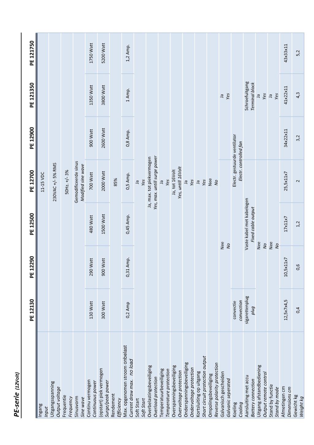
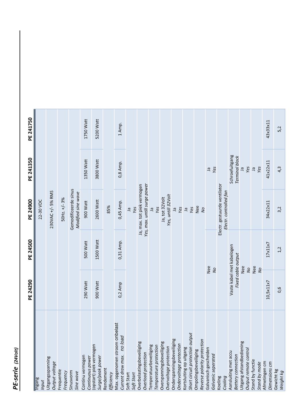
2 Nederlands INTRODUCTIE Lees deze gebruiksaanwijzing geheel door alvorens het apparaat te gaan gebruiken. Op bladzijde 19 en 20 zijn de technische specificaties te vinden. Deze DC-AC inverter vormt een 12/24 Volts gelijkspanning om naar 230Volt / 50Hz wisselspanning. Hierdoor is het mogelijk om, met behulp van een accu, apparatuur te laten werken waar normaal gesproken een 230VAC/50Hz netwerk voor nodig is. Let op! Ga voor gebruik altijd eerst na of het desbetreffende apparaat functioneert op een gemodificeerde sinus spanning. Belangrijk Controleer altijd het werkelijk opgenomen vermogen van de apparatuur. Hou tevens rekening met de opstartpieken. Controleer of deze waarden binnen de capaciteitsgrenzen van de inverter vallen. Deze inverters bevatten een soft-start. Hierdoor zal de uitgangsspanning van 230VAC pas na ongeveer 30sec. aanwezig zijn. Voor de modellen vanaf 900Watt is optioneel de afstandsbediening RC 010 te verkrijgen, waarmee op afstand de inverter bediend kan worden. INSTALLATIE Montage De inverter dient in een ruimte gemonteerd te worden waarbij rekening gehouden wordt met het volgende: - Laat aan alle zijdes om de inverter voldoende ruimte open (min.10cm) voor luchtcirculatie. Zorg tevens voor ventilatie openingen. - De omgevingstemperatuur dient tussen de 0ºC en 40ºC te zijn. De optimale temperatuur ligt tussen de 15ºC en 25ºC. - Monteer de inverter op een droge plaats waar vocht en vervuiling geen kans maakt. - Houd de inverter buiten bereik van kinderen. - Een werkende omvormer geeft gevaarlijke spanning af. - Gebruik de inverter niet op plaatsen waar gassen vrij komen of vlambare materialen liggen opgeslagen. Een warme behuizing is normaal tijdens belasting van de inverter. Aansluiting Belangrijk - Sluit geen 230VAC (stroombron) aan op de uitgang van de inverter. Dit heeft grote schade aan de inverter tot gevolg. - Controleer vóór u de verbinding met de accu maakt of verbreekt, of de inverter uit staat. 2
3 Nederlands Sigarettenplug (PE 12130) Sluit de plug aan op een passende 12Volts uitgang. Vaste kabelingang (inverters 290Watt t/m 700 Watt) - Monteer de rode aansluitkabel op de pluspool en de zwarte aansluitkabel op de min pool van de accu. Let op dat u de juiste kabel op de juiste pool aansluit. De interne zekeringen raken defect als u de inverter ompoolt. De inverter moet dan voor reparatie en controle teruggestuurd worden naar de fabrikant. De reparatiekosten vallen dan niet onder de garantie. - Bij aansluiting met de accu kan er een vonk vrijkomen, dit door het laden van de inwendige condensator. Schroefaansluiting (inverters vanaf 900Watt) - Sluit d.m.v. een kabeloog een rode kabel aan op de + ingang van de inverter en een zwarte kabel op de ingang. Houdt hiervoor onderstaande kabeldiktes aan. - Let op dat u de juiste kabel op de juiste pool aansluit. De interne zekeringen raken defect als u de inverter ompoolt. De inverter moet dan voor reparatie en controle teruggestuurd worden naar de fabrikant. De reparatiekosten vallen dan niet onder de garantie. - Bij aansluiting met de accu kan er een vonk vrijkomen, dit door het laden van de inwendige condensator. 0-1mtr. 1-2mtr. 2-3mtr. PE mmq 35mmq 50mmq PE mmq 50mmq 70mmq PE mmq 70mmq 90mmq PE mmq 16mmq 25mmq PE mmq 25mmq 35mmq PE mmq 35mmq 50mmq Houdt de aansluitkabels zo kort mogelijk! Belangrijk Monteer een zekering tussen de plus aansluitkabels bij de types vanaf 290Watt. Houd hiervoor onderstaande tabel aan. Model Zekering Model Zekering PE Amp. PE Amp. PE Amp. PE Amp. PE Amp. PE Amp. PE Amp. PE Amp. PE Amp. PE Amp. PE Amp. 3
4 Nederlands IN GEBRUIK Controleer of de kabels goed gemonteerd zijn. Zet de inverter aan met de aan/uit schakelaar. Modellen t/m 700Watt De indicatie led In licht op. Dit wil zeggen dat het voltage op de ingang normaal is. Indien deze spanning te hoog of the laag is, start de inverter niet op. Na ongeveer 30 seconden zal de led Out gaan branden. De 230VAC is dan aanwezig. De inverter is klaar voor gebruik. Modellen vanaf 900Watt De indicatie led Power on, battery in use licht op. Dit wil zeggen dat het voltage op de ingang normaal is. Indien deze spanning te hoog of the laag is, start de inverter niet op. De led load testing, AC output normal gaat knipperen. Na ongeveer 30 seconden zal de led continu gaan branden. De 230VAC is dan aanwezig. De inverter is klaar voor gebruik. De gele indicatie led half load gaat branden als de inverter voor ongeveer 50% belast is. De rode indicatieled full load brandt als de inverter zijn volledige capaciteit levert. Als u de inverter voor langere tijd niet gebruikt adviseren wij u om deze los te koppelen van de accu (bv. tijdens winterstalling) No load shut down schakelaar De zwaardere modellen, vanaf 900Watt, hebben een schakelaar om de inverter in een energie besparende stand te zetten. Indien de schakelaar op on staat zal de inverter als er langer dan ongeveer 1 minuut geen belasting aanwezig is, in deze stand-by modus komen te staan. Het verbruik wordt hiermee gereduceerd naar 0,1Amp. De inverter blijft continu aan staan als de schakelaar op de off stand staat. Beveiligingen Soft start Als de inverter aanstaat en er wordt een apparaat ingeschakeld met een hoge opstartpiek dan zal de inverter zich herstarten (door de overbelastingsbeveiliging) en daarna d.m.v. de soft start het betreffende apparaat opstarten. Let echter wel op dat de opstartpiek van het apparaat niet boven de piek uit komt die de inverter kan verwerken. Kortsluiting op de uitgang De inverters t/m 700Watt zijn slaan af als er op de uitgang een kortsluiting aanwezig is. De inverter herstart zichzelf nadat het probleem verholpen is. De modellen vanaf 900Watt kunnen niet tegen een kortsluiting en zullen voor reparatie retour moeten worden gestuurd. Temperatuur De inverter slaat af als de interne temperatuur hoger is dan 70ºC en herstart zichzelf weer bij +/- 50ºC. 4
5 Nederlands Overspanning De inverter start niet op of schakelt zichzelf uit als de ingangsspanning hoger is dan 15Volt (12Volt systeem) of 30Volt (24Volt systeem). Als de inverter in deze beveiliging is getreden dan dient deze handmatig herstart te worden. Let op: De max. ingangsspanning die de inverter kan verdragen is 16Volt (12Volt systeem) of 32Volt (24Volt systeem). Indien de aangeboden ingangsspanning nog hoger is, zal de inverter defect gaan. De reparatiekosten vallen dan niet onder de garantie. Onderspanning De inverter start niet op als de ingangsspanning lager is dan 10Volt (12Volt systeem) of 20Volt (24Volt systeem). Als tijdens het gebruik de ingangsspanning zakt onder deze waarden, dan zal de inverter zichzelf uitschakelen. Overbelasting De inverter slaat af bij een overschrijding van het maximale vermogen en zal zichzelf daarna herstarten. Let op: de overbelastingsbeveiliging werkt alleen bij het maximaal vermogen, niet voor het piervermogen. Als het piekvermogen overschreden wordt zal de inverter defect raken. De reparatiekosten vallen dan niet onder de garantie. PROBLEEM OPLOSSER Probleem (mogelijke) oorzaak Oplossing Slecht of geen contact met de accu. Controleer de verbindingen. Geen uitgang (230VAC). Er branden geen led s. Te hoog/laag ingangsvoltage of slechte conditie accu. Zekering tussen de aansluitkabel defect. Temperatuurbeveiliging is in werking. Interne zekeringen defect. Te dunne kabels gebruikt. Er treedt een te groot spanningsverlies op. Controleer de ingangsspanning of vervang de accu bij een slechte conditie Controleer/vervang de zekering. De inverter zal automatisch weer in werking treden als deze voldoende is afgekoeld. Controleer of de inverter voldoende kan koelen. Retourneer de inverter naar de fabrikant of uw dealer. Controleer de kabeldikte met de tabel. Monteer dikkere kabels. >>> 5
6 Nederlands De indicatie led AC output normal brandt, maar de gebruikers starten niet op. Een te lage uitgangspanning. Accucapaciteit te gering om het gevraagde vermogen te leveren. Te zware belasting. Te dunne kabels gebruikt. Er treedt een te groot spanningsverlies op. U meet de spanning met een normale Voltmeter. Een te lage ingangspanning. Monteer een accu(set) met een hogere capaciteit. Zorg ervoor dat de belasting niet hoger is dan de opgegeven waarden. Controleer de kabeldikte met de tabel. Monteer dikkere kabels. De uitgangsspanning van een gemodificeerde sinusvorm is niet te meten met een normale Voltmeter. Hiervoor is een True RMS meter nodig. Zorg ervoor dat de ingangsspanning hoger dan 11,5Volt (12V.syst.) of 23Volt (24V. syst.) blijft. Laadt de accu bij. ACCESSOIRES RC 010S Afstandsbediening. Incl. 10mtr. snoer. CP 823 Omschakelbox tussen inverter en netspanning/aggregaat. Zie pag. 2 Voor meer informatie, kijk op onze website: ONDERHOUD De inverters uit de PE serie hebben weinig onderhoud nodig. Houd de inverter vrij van stof en alle andere vormen van vervuiling. Maak de buitenkant inverter regelmatig schoon met licht vochtige doek. Controleer periodiek: - alle kabels en verbindingen. Vervang beschadigde kabels direct. - de ventilatie openingen Let op: zorg ervoor dat de inverter uit staat tijdens onderhoudswerkzaamheden! 6
7 Nederlands GARANTIE EN SERVICE Raadplaag altijd eerst de probleemoplosser en de overige uitleg in deze gebruiksaanwijzing voordat u de inverter retourneert. Indien een defect/probleem door middel van deze gebruiksaanwijzing opgelost had kunnen worden, dan zijn wij genoodzaakt om de gemaakte kosten door te berekenen. In geval van een defect kunt u de inverter terug brengen naar uw leverancier of rechtstreeks retourneren naar het adres op de achterzijde. Het apparaat dient gefrankeerd op gestuurd te worden. Op deze inverters wordt 1 jaar garantie verleend vanaf verkoopdatum en alleen op arbeid en onderdelen van de reparatie. De garantieduur is alleen van kracht als bij de reparatie de (kopie) aankoopbon overhandigd is. De garantie vervalt bij foutief gebruik of aansluiting en bij reparatiewerken door derden. Probeer onder geen geding de inverter zelf te repareren. Het gebruik van deze inverters is de verantwoordelijkheid van de klant. De fabrikant kan niet aansprakelijk worden gesteld voor (vervolg)schade. 7
8 English INTRODUCTION Read this user manual completely before using the device. On page 19 and 20 you will find the technical specifications of the PE inverters. This DC-AC inverter converts a 12/24 Volts DC voltage into a 230 Volts/50Hz AC voltage. With this device it is possible to use a battery to supply equipment that normally requires a 230VAC/50Hz mains supply. Attention! Before using this device, always check that the equipment can function with a modified sine wave voltage. Important Always check the actual power rating of the equipment. In addition, bear in mind the start-up peaks. Check whether these values are within the capacity limits of the inverter. These inverters feature a soft start. This means that the 230 VAC output voltage will only be present after approximately 30 sec. A remote control, for controlling the inverter remotely, is available as an optional extra for the models of 900 Watts and higher. INSTALLATION Mounting The inverter must be mounted in a space that complies with the following: - Leave enough space on all sides of the inverter (min. 10 cm) for air circulation. In addition, make sure that there are ventilation vents. - The ambient temperature must be between 0ºC and 40ºC. The optimum temperature is between 15ºC and 25ºC. - Mount the inverter in a dry place where there is no chance of it being affected by moisture or dirt. - Keep the inverter out of the reach of children. - A working inverter produces a dangerous voltage. - Do not use the inverter in places where gases are released or flammable materials are stored. It is normal that the inverter case is warm when there is a load on the inverter. Connection Important - Do not connect 230 VAC (current source) to the output of the inverter. This will cause extensive damage to the inverter. - Before connecting or disconnection the battery, check that the inverter is turned off. 8 Cigarette lighter plug (PE 12130) Connect the plug to a suitable 12Volts output. Fixed cable output (inverters of 290 Watts up to and including 700 Watts) - Connect the red connection cable to the positive pole and the black connection cable to the negative pole of the battery. Make sure that the correct cable is connected to the
9 English correct pole. The internal fuses will be blown of you reverse the poles on the inverter. In this case, the inverter must be returned to the manufacturer for repair and inspection, and the repair costs are not covered by the guarantee. - When the battery is connected a spark may be generated due to the internal capacitor being loaded. Screw connector (inverters of 900 Watts and higher) - Using cable eyes, connect the red cable to the + output on the inverter and the black cable to the output. When doing this, use the cable thicknesses specified below. - Make sure that you connect the correct cable to the correct pole. The internal fuses will be blown of you reverse the poles on the inverter. In this case, the inverter must be returned to the manufacturer for repair and inspection, and the repair costs are not covered by the guarantee. - When the battery is connected a spark may be generated due to the internal capacitor being loaded. 0-1mtr. 1-2mtr. 2-3mtr. PE mmq 35mmq 50mmq PE mmq 50mmq 70mmq PE mmq 70mmq 90mmq PE mmq 16mmq 25mmq PE mmq 25mmq 35mmq PE mmq 35mmq 50mmq Keep the connection cables as short as possible! Important Fit a fuse between the positive connection cables of the 290 Watts and higher types. Use the table given below to determine the values. Model Fuse Model Fuse PE Amp. PE Amp. PE Amp. PE Amp. PE Amp. PE Amp. PE Amp. PE Amp. PE Amp. PE Amp. PE Amp. IN USE Check that the cables have been mounted correctly. Turn the inverter on by means of the on/off switch. Models up to and including 700 Watts The indicator LED In is on. This means that the voltage on the input is normal. If this voltage is too high or too low then the inverter will not start up. After approximately 30 seconds, the LED Out turns on. This means that the 230 VAC is present. The inverter is ready for use. 9
10 English Models of 900 Watts and higher The indicator LED Power on, battery in use is on. This means that the voltage on the input is normal. If this voltage is too high or too low then the inverter will not start up. The LED load testing, AC output normal starts to flash. After approximately 30 seconds the LED will be on continuously. This means that the 230 VAC is present. The inverter is ready for use. The yellow indicator LED half load turns on when the inverter is approximately 50% loaded. The red indicator LED full load turns on when the inverter is working at its full capacity. If you are not planning to use the inverter for a long period of time, then we advise you to disconnect it from the battery (e.g. during winter storage) No load shut down switch The heavier models of 900 Watts and higher have a switch to switch the inverter to an energy saving mode. If the switch is on and there is no load on the inverter for approximately 1 minute, then the inverter will revert to this standby mode. The current draw is then decreased to 0,1Amp. If the switch is in the off position, then the inverter remains on continuously. Protections Soft start If the inverter is on and equipment is switched on that has a high start-up peak, the inverter will restart itself (due to the overload protection) and then start up the equipment in question by means of a soft start. However, you should ensure that the start up peak of the equipment does not exceed the value that the inverter can handle. Short-circuit on the output The inverters up to and including 700 Watts versions, switch off if the output is shortcircuited. The inverter restarts itself when the problem has been solved. The models of 900 Watts and higher cannot handle a short-circuit and must be returned for repair if this occurs. Temperature The inverter switches off when the internal temperature exceeds 70ºC and restarts itself when the temperature drops to approximately 50ºC. Over-voltage If the input voltage is higher than 15 Volts (12 Volts system) or 30 Volts (24 Volts system) then the inverter will not start up or will switch itself off. If the inverter has entered this protection mode then it must be restarted manually. Important The maximum input voltage that the inverter can tolerate is 16 Volts (12 Volts system) or 32 Volts (24 Volts system). If the voltage that is supplied is higher than this then the inverter will break. In this case the repair costs are not covered by the guarantee. Under-voltage If the input voltage is lower than 10 Volts (12 Volts system) or 20 Volts (24 Volts system) then the inverter will not start up. If the input voltage drops below this value during operation, then the inverter will switch itself off. 10
11 English Overload If the maximum power is exceeded then the inverter will switch off and will restart itself afterwards. Important: The overload protection only works with continuous power and not with peak power. If the peak load on the inverter is exceeded then the inverter will break! In this case the repair costs are not covered by the guarantee. PROBLEM SOLVER Problem (possible) cause Solution Bad contact or no contact with the battery. Check the connections. No output (230VAC). There are no LEDs on. The indicator LED AC output normal is on but the users do not start up. Input voltage too high/low Or battery in bad condition. Fuse between the connection cables is blown. Temperature protection has been tripped. Internal fuses are blown. Cables that are too thin have been used. The voltage loss is too large. The battery capacity is too low to supply the required power. The load is too large. Cables that are too thin have been used. The voltage loss is too large. Check the input voltage or replace the battery if it is in bad condition. Check/replace the fuse The inverter will start to work again automatically when it has cooled down sufficiently. Check that the inverter can cool down sufficiently. Return the inverter to the manufacturer or your dealer. Check the diameter of the cables against the values given in the table. Fit thicker cables. Use a battery(set) with a higher capacity. Ensure that the load is not greater than the specified value. Check the diameter of the cables against the values given in the table. Fit thicker cables. 11
12 English Output voltage is too low. You are measuring the voltage with a normal voltmeter. Input voltage is too low. The voltage of a modified sine wave cannot be measured with a normal voltmeter. To perform this measurement a true RMS voltmeter is required. Ensure that the input voltage remains higher then 11.5Volts (12 V system) or 23Volts (24 V system). ACCESSORIES RC 010S Remote control. Incl. 10mtr. cable CP 823 Automatic switch between inverter and mains or generator. More information on our website MAINTENANCE To keep your inverter operating properly, there is very little maintenance required. You should clan the exterior periodically with a damp cloth to prevent accumulation of dust and dirt. Also check periodically: - All wires and connections. Replace damaged wires immediately. - The ventilation vents. ATTENTION: turn off the inverter before you start the maintenance activities. WARRANTY AND SERVICE Before sending back the inverter, always advice the Trouble Shooter and other information in this manual firstly. If a problem could have been solved by means of this manual, we are obligated to charge the repair/research costs. In case of a malfunction, the inverter can be send to us directly or you can choose to arrange the return with your dealer. The inverter must be send prepaid. The PE inverters carry a one-year warranty. This warranty only covers the costs of parts and labour for the repair. The warranty period is only valid when the purchase ticket is handed over with the repair. The warranty will lapse when a third party has attempted to repair the inverter or when the inverter is not installed or used in accordance with the instructions. Do not attempt to repair the inverter yourselves. The manufacturer cannot be hold responsible for any damage resulting from use of the PE inverter. 12
13 Deutsch INTRODUKTION Lesen Sie bitte diese Gebrauchsanleitung vollständig durch, bevor Sie das Gerät verwenden. Die technischen Spezifikation sind den letzten Seiten zu entnehmen. Dieser DC-AC-Wechselrichter wandelt 12/24 Volt Gleichspannung in Wechselspannung mit 230 Volt / 50 Hz um. Mit Hilfe einer Batterie können so Geräte betrieben werden, für die im Normalfall ein Stromnetz mit 230 V AC/50 Hz erforderlich wäre. Achtung! Prüfen Sie immer vor Inbetriebnahme, ob das betreffende Gerät mit einer modifizierten Sinusspannung funktioniert. Wichtig Kontrollieren Sie immer die tatsächliche Leistungsaufnahme des Geräts. Berücksichtigen Sie dabei auch die Einschaltspitzen. Kontrollieren Sie, ob diese Werte innerhalb der Kapazitätsgrenzen des Wechselrichters liegen. Diese Wechselrichter haben eine Soft-Start-Funktion. Dadurch ist die Ausgangsspannung von 230 V AC erst nach ungefähr 30 Sekunden vorhanden. Für die Modelle ab 900 Watt ist als Option die Fernbedienung RC 010 erhältlich, mit der der Wechselrichter fernbedient werden kann. INSTALLATION Montage Der Wechselrichter muss in einem Raum montiert werden, wobei Folgendes zu berücksichtigen ist: - Lassen Sie auf allen Seiten rund um den Wechselrichter ausreichend Freiraum (min. 10cm) für Luftzirkulation. Sorgen Sie auch für Belüftungsöffnungen. - Die Umgebungstemperatur muss zwischen 0 ºC und 40 ºC liegen. Die optimale Temperatur liegt zwischen 15 ºC und 25 ºC. - Bringen Sie den Wechselrichter an einem trockenen Ort an, wo er vor Feuchtigkeit und Schmutz geschützt ist. - Bringen Sie den Wechselrichter außerhalb der Reichweite von Kindern an. - Im Betrieb gibt ein Wechselrichter gefährliche Spannung ab. - Verwenden Sie den Wechselrichter nicht an Orten, wo Gase freigesetzt oder entflammbare Materialien aufbewahrt werden. Ein warmes Gehäuse ist bei Belastung des Wechselrichters normal. Anschluss Wichtig - Schließen Sie keine Stromquelle mit 230VAC an den Ausgang des Wechselrichters an. Dies verursacht schwere Schäden am Wechselrichter. - Kontrollieren Sie, bevor Sie die Verbindung mit der Batterie herstellen, ob der Wechselrichter ausgeschaltet ist. Zigarettenanzünder-Stecker (130Watt) Schließen Sie den Stecker an einen passenden 12/24-Volt-Ausgang an. 13
14 Deutsch Fester Kabelausgang (Wechselrichter 290 bis 700 Watt) - Schließen Sie das rote Anschlusskabel an den Pluspol und das schwarze Anschlusskabel an den Minuspol der Batterie an. Achten Sie darauf, das richtige Kabel an jeden Pol anzuschließen. Die internen Sicherungen brennen durch, wenn Sie den Wechselrichter verpolen. Der Wechselrichter muss dann zur Reparatur und Kontrolle an den Hersteller eingeschickt werden. Die Reparaturkosten fallen nicht unter die Garantie. - Beim Anschluss an die Batterie kann durch das Aufladen des internen Kondensators ein Funke entstehen. Schraubanschluss (Wechselrichter ab 900 Watt) - Schließen Sie mit einer Kabelöse ein rotes Kabel an den Plusausgang (+) und ein schwarzes Kabel an den Minusausgang (-) des Wechselrichters an. Verwenden Sie dafür die folgenden Kabeldicken. - Achten Sie darauf, das richtige Kabel an jeden Pol anzuschließen. Die internen Sicherungen brennen durch, wenn Sie den Wechselrichter verpolen. Der Wechselrichter muss dann zur Reparatur und Kontrolle an den Hersteller eingeschickt werden. Die Reparaturkosten fallen nicht unter die Garantie. - Beim Anschluss an die Batterie kann durch das Aufladen des internen Kondensators ein Funke entstehen. 0-1mtr. 1-2mtr. 2-3mtr. PE mmq 35mmq 50mmq PE mmq 50mmq 70mmq PE mmq 70mmq 90mmq PE mmq 16mmq 25mmq PE mmq 25mmq 35mmq PE mmq 35mmq 50mmq Halten Sie die Anschlusskabel möglichst kurz! Wichtig Bringen Sie bei den Modellen ab 290 Watt eine Sicherung in der Plus-Leitung der Anschlusskabel an. Beachten Sie dafür die folgende Tabelle. Model Sicherung Model Sicherung PE Amp. PE Amp. PE Amp. PE Amp. PE Amp. PE Amp. PE Amp. PE Amp. PE Amp. PE Amp. PE Amp. 14
15 Deutsch IN BETRIEB Kontrollieren Sie, ob die Kabel richtig angeschlossen sind. Schalten Sie den Wechselrichter am Ein/Aus-Schalter ein. Modelle bis 700 Watt Die Kontroll-LED In leuchtet auf. Das bedeutet, dass die Spannung am Eingang normal ist. Falls diese Spannung zu hoch oder zu niedrig ist, startet der Wechselrichter nicht. Nach ungefähr 30 Sekunden leuchtet die LED Out auf. Die 230 V AC sind dann vorhanden. Der Wechselrichter ist einsatzbereit. Modelle ab 900 Watt Die Kontroll-LED power on, battery in use leuchtet auf. Das bedeutet, dass die Spannung am Eingang normal ist. Falls diese Spannung zu hoch oder zu niedrig ist, startet der Wechselrichter nicht. Die LED load testing, AC output normal beginnt zu blinken. Nach ungefähr 30 Sekunden leuchtet die LED kontinuierlich. Die 230 VAC sind dann vorhanden. Der Wechselrichter ist einsatzbereit. Die gelbe Kontroll-LED half load leuchtet auf, wenn der Wechselrichter zu ungefähr 50 % belastet ist. Die rote Kontroll-LED full load leuchtet, wenn der Wechselrichter seine vollständige Kapazität liefert. Wenn Sie den Wechselrichter längere Zeit (z.b. in der Überwinterung) nicht nutzen, empfehlen wir, ihn von der Batterie zu trennen. Schalter No load shut down Die stärkeren Modelle (ab 900 Watt) haben einen Schalter, um den Wechselrichter in einen energiesparenden Zustand zu versetzen. Wenn der Schalter auf on steht, schaltet der Wechselrichter, wenn länger als ungefähr eine Minute keine Last vorhanden ist, in diesen Ruhemodus um. Der Wechselrichter bleibt kontinuierlich eingeschaltet, wenn der Schalter in der Stellung off steht. Sicherheitseinrichtungen Soft-Start Wenn der Wechselrichter eingeschaltet ist und ein Gerät mit einer hohen Einschaltspitze eingeschaltet wird, startet der Wechselrichter sich neu (durch den Überlastschutz) und startet dann durch den Soft-Start das betreffende Gerät. Achten Sie jedoch darauf, dass die Einschaltspitze des Geräts nicht die Spitzenbelastung überschreitet, die der Wechselrichter verarbeiten kann. Kurzschluss am Ausgang Die Wechselrichter bis 700 Watt schalten ab, wenn am Ausgang ein Kurzschluss vorhanden ist. Der Wechselrichter startet selbständig wieder, nachdem das Problem behoben ist. Die Modelle ab 900 Watt sind nicht kurzschlussfest und müssen zur Reparatur an den Hersteller eingeschickt werden. Temperatur Der Wechselrichter schaltet sich ab, wenn die Innentemperatur 70 ºC überschreitet und startet bei +/- 50 ºC selbständig erneut. 15
16 Deutsch Überspannung Der Wechselrichter startet nicht oder schaltet sich selbständig aus, wenn die Eingangsspannung höher als 15 Volt (12-Volt-System) / 30 Volt (24-Volt-System) ist. Wenn diese Sicherheitseinrichtung im Wechselrichter aktiviert worden ist, muss der Wechselrichter von Hand neu gestartet werden. Wichtig Der Wechselrichter verträgt eine maximale Eingangsspannung von 16 Volt (12-Volt- System)/32 Volt (24-Volt-System). Wenn die anliegende Eingangsspannung noch höher ist, wird der Wechselrichter beschädigt. Die Reparaturkosten fallen nicht unter die Garantie. Unterspannung Der Wechselrichter startet nicht oder schaltet sich selbständig aus, wenn die Eingangsspannung niedriger als 10 Volt (12-Volt-System) / 20 Volt (24-Volt-System) ist. Wenn die Eingangsspannung im Betrieb unter die genannten Werte sinkt, schaltet sich der Wechselrichter selbständig aus. Überlastung Der Wechselrichter schaltet sich bei Überschreitung der Maximalleistung ab und startet danach selbständig wieder. Wichtig Der Überlastschutz funktioniert nur bei Dauerleistung, nicht für die Spitzenleistung. Bei Überschreitung der Spitzenbelastung wird der Wechselrichter beschädigt! Die Reparaturkosten fallen nicht unter die Garantie. PROBLEMLÖSER Problem (Mögliche) Ursache Lösung Die Kontroll-LED AC output normal leuchtet, aber die Benutzer starten nicht. Ausgangsspannung zu niedrig. Batteriekapazität zu gering, um die verlangte Leistung zu liefern. Zu hohe Belastung. Zu dünne Kabel verwendet. Der Spannungsabfall ist zu groß. Sie messen die Spannung mit einem normalen Voltmeter. Eine/n Batterie(satz) mit höherer Kapazität montieren. Dafür sorgen, dass die Belastung die angegebenen Werte nicht überschreitet. Die Kabeldicke anhand der Tabelle kontrollieren. Dickere Kabel verwenden. Die Ausgangsspannung einer modifizierten Sinusform lässt sich mit einem normalen Volt-meter nicht messen. Dafür ist ein true RMS -Messgerät erforderlich. Eingangsspannung zu niedrig. Dafür sorgen, dass die Eingangs spannung zwischen 11,5/23 Volt bleibt. Die Batterie nachladen. 16
17 Deutsch Keine Ausgangsspannung (230 V AC). Es leuchten keine LEDs. Schlechter oder kein Kontakt mit der Batterie. Zu hohe/niedrige Eingangsspannung oder schlechter Batteriezustand. Sicherung im Anschlusskabel defekt. Überhitzungsschutz wurde aktiviert. Interne Sicherungen defekt. Zu dünne Kabel verwendet. Der Spannungsabfall ist zu groß. Die Verbindungen kontrollieren. Die Eingangsspannung Kontrollieren oder bei schlechtem Zustand ersetzen. Die Sicherung kontrollieren / auswechseln. Der Wechselrichter geht automatisch wieder in Betrieb, wenn er ausreichend abgekühlt ist. Kontrollieren, ob sich der Wechselrichter ausreichend abkühlen kann. Den Wechselrichter an den Hersteller oder Ihre Fachhändler einschicken. Die Kabeldicke anhand der Tabelle kontrollieren. Dickere Kabel verwenden. ZUBEHÖR RC 010S Fernbedienung inkl. 10mtr. Kabel. CP 823 Dieses Gerät schaltet automatisch zwischen Netz/Generator und Inverter. WARTUNG Die inverter aus die PE-Serie müssen nicht oft gewartet werden. Halten Sie den Inverter staub- und schmutzfrei. Säubern Sie die Außenseite des Inverters regelmäßig mit einem leicht feuchten Tuch. Kontrollieren Sie regelmäßig: - Alle Kabel und Anschlüsse. Ersetzen Sie beschädigte Kabel sofort. - Die Lüftungsöffnungen. Achtung: Sorgen Sie dafür, dass der Inverter ausgeschaltet ist! 17
18 Deutsch GARANTIE Schauen Sie immer zuerst in die Fehlerbehebung oder in die sonstigen Erläuterungen dieser Gebrauchsanweisung, bevor Sie das Gerät zurückgeben. Falls ein Defekt/Problem mit dieser Gebrauchsanweisung hätte behoben werden können, sind wir gezwungen die entstandenen Kosten in Rechnung zu stellen. Im Fall eines Defekt können Sie das Gerät nach Ihrem Händler zurückbringen oder direkt an die Adresse auf der Rückseite schicken. Schicken Sie das Gerät immer frankiert ab. Die PE inverter - Serie wird mit einer einjährigen Garantie geliefert, die ab dem Verkaufsdatum gilt. Diese Garantie bezieht sich nur auf die Komponenten beziehungsweise den Arbeitslohn für die Reparatur. Die Garantiezeit ist nur gültig, wenn bei der Reparatur der Kassenbon vorgelegt wird. Die Garantie erlischt, wenn Reparaturarbeiten von Drittparteien durchgeführt werden, wenn der Wechselrichter unsachgemäß verwendet oder verkehrt angeschlossen wurde. Der Kunde verwendet diesen Inverter in eigener Verantwortung. Hersteller und Zulieferer sind für (Folge-) Schäden nicht haftbar. 18
19 19
20 20
21 21
22 Xenteq BV Banmolen ET Meijel Nederland Tel: +31 (0) Fax: +31 (0) V1.4
PC-series. P a g i n a 2. P a g e 7
 PC-series Gebruiksa anw i jz i ng P a g i n a 2 Users manu al P a g e 7 NL E N 1 NL INTRODUCTIE Lees deze gebruiksaanwijzing aandachtig, alvorens u het apparaat gaat gebruiken. Op de laatste bladzijde
Gebruiksaanwijzing. ES-serie
 Gebruiksaanwijzing ES-serie Lees deze gebruiksaanwijzing geheel door voordat u het apparaat gaat gebruiken. In de bijlagen vindt u de technische specificaties van dit apparaat. Deze DC-AC inverter vormt
Monteer de diodeverdeler op een koele plaats, niet in de directe omgeving van de motor of andere apparatuur die warmte afgeeft.
 NL- Gebruiksaanwijzing Pagin a 2 GB Directions for use Page 4 DE Gebrauchsanweisung Seite 6 1 Nederlands INTRO DU C TI E De diodeverdelers uit de DB-serie zorgen voor een perfecte scheiding tussen meerdere
Quick start guide. Powerbank MI Mah. Follow Fast All rights reserved. Page 1
 Quick start guide Powerbank MI 16.000 Mah Follow Fast 2016 - All rights reserved. Page 1 ENGLISH The Mi 16000 Power Bank is a very good backup option for those on the move. It can keep you going for days
PB 1108 IPC P a g i n a 2. P a g e 6. P a g e 1 0
 PB 1108 IPC 1205 Gebruiksa anw i jz i ng P a g i n a 2 Use rs manual P a g e 6 Bedienung sanlei tung P a g e 1 0 NL EN DE NL INTRODUCTIE Lees deze gebruiksaanwijzing aandachtig, alvorens u het apparaat
PIR DC-SWITCH. DC Passive infra-red Detector. Model No. PDS-10 GEBRUIKSAANWIJZING/INSTRUCTION MANUAL
 PIR DC-SWITCH DC Passive infra-red Detector Model No. PDS-10 GEBRUIKSAANWIJZING/INSTRUCTION MANUAL Please read this manual before operating your DETECTOR PIR DC-Switch (PDS-10) De PDS-10 is een beweging
SP-series. Gebruiksaanwijzing NL
 SP-series Gebruiksaanwijzing NL INTRODUCTIE NL Lees deze gebruiksaanwijzing geheel door alvorens het apparaat te gaan gebruiken. In de bijlagen vindt u de technische specificaties van dit apparaat. Deze
SK-series. NL- Gebruiksaanwijzing. GB - Users manual. DE Gebrauchsanweisung W att. Pagina 2. Page 9. Seite 16
 SK-series 7 00 W att NL- Gebruiksaanwijzing Pagina 2 GB - Users manual Page 9 DE Gebrauchsanweisung Seite 16 Nederlands INTRODUCTIE Lees deze gebruiksaanwijzing geheel door alvorens het apparaat te gaan
ES -series. Gebruiksaanwijzing - NL. Users manual - EN. Gebrauchsanweisung - DE. Pagina 2. Page 12. Seite 22
 ES -series Gebruiksaanwijzing - NL Pagina 2 Users manual - EN Page 12 Gebrauchsanweisung - DE Seite 22 NEDERLANDS INTRODUCTIE Lees deze gebruiksaanwijzing geheel door alvorens het apparaat te gaan gebruiken.
ES -series. Gebruiksaanwijzing. Users manual. Gebrauchsanweisung. Pagina 2. Page 10. Seite 18
 ES -series Gebruiksaanwijzing NL Pagina 2 Users manual EN Page 10 Gebrauchsanweisung Seite 18 DE INTRODUCTIE NL Lees deze gebruiksaanwijzing geheel door alvorens het apparaat te gaan gebruiken. In de bijlagen
Universe Square Double / Triple
 Universe Square Double / Triple NL Installatie handleiding DE Installationsanleitung EN Installation manual 1 NL Informatie / DE Information/ EN Information Veiligheidsinformatie Onderbreek altijd de stroomtoevoer
Citadel Composition. NL Installatie handleiding DE Installationsanleitung EN Installation manual
 Citadel Composition NL Installatie handleiding DE Installationsanleitung EN Installation manual 1 NL Informatie / DE Information/ EN Information Veiligheidsinformatie Onderbreek altijd de stroomtoevoer
EU Declaration of Conformity and safety instructions EU Conformiteitsverklaring en veiligheidsinstructies ISC 230B
 EU Declaration of Conformity and safety instructions EU Conformiteitsverklaring en veiligheidsinstructies ISC 230B Explosion safety instructions (Ex) (EN) ISC230B is approved for use outside the explosion-hazardous
Universe. NL Installatie handleiding DE Installationsanleitung EN Installation manual
 Universe NL Installatie handleiding DE Installationsanleitung EN Installation manual 1 NL Informatie / DE Information/ EN Information Veiligheidsinformatie Onderbreek altijd de stroomtoevoer door verwijderen
EU Declaration of Conformity and safety instructions EU Conformiteitsverklaring en veiligheidsinstructies
 EU Declaration of Conformity and safety instructions EU Conformiteitsverklaring en veiligheidsinstructies Battery operated UNICOM 300 N51 UNICOM 300 met batterijvoeding N51 Explosion safety instructions
Anleitung SWS Wireless Display
 Anleitung SWS Wireless Display E A B C D F G H I J K L M N O A B C D E F G H Massage ein Massage aus Abnahme Massage Intensität Zunahme Massage Intensität Taschenlampe Display Taschenlampe ein/aus Bodenbeleuchtung
Mira. NL Installatie handleiding. DE Installationsanleitung. EN Installation manual
 Mira NL Installatie handleiding DE Installationsanleitung EN Installation manual 1 Mira; NL Informatie / DE Information / EN Information Veiligheidsinformatie Sicherheitshinweise Safety information Onderbreek
HANDLEIDING - ACTIEVE MOTORKRAAN
 M A N U A L HANDLEIDING - ACTIEVE MOTORKRAAN MANUAL - ACTIVE MOTOR VALVE Model E710877 E710878 E710856 E710972 E710973 www.tasseron.nl Inhoud / Content NEDERLANDS Hoofdstuk Pagina NL 1 ALGEMEEN 2 NL 1.1
Ixion. NL Installatie handleiding. DE Installationsanleitung. EN Installation manual
 Ixion NL Installatie handleiding DE Installationsanleitung EN Installation manual 1 Orion; NL Informatie / DE Information / EN Information Veiligheidsinformatie Sicherheitshinweise Safety information Onderbreek
Handleiding Wallwash Downlight
 Handleiding Wallwash Downlight 3000K WARM 3900 4000K COOL 4200 5 JAAR 43 WATT 50.000 UUR CRI >82 >10.000 x < 0,01 90-60 GRADEN PF 0.95 VAC 230 HANDLEIDING IL-DWW43K3 / IL-DWW43K4 Installatie INPUT: 100-240V
ES-S7A. Außensirene. www.etiger.com
 ES-S7A Außensirene www.etiger.com DE Merkmale - Funkverbindung für eine einfache Installation - Radiofrequenzsicherheit des Zubehörs: über eine Million Codekombinationen - EEPROM-Informationsschutz, keine
Für ProLux Wechselrichter Reiner Sinus
 Gebrauchsanweisung User Manual Gebruiksaanwi jzing Für ProLux Wechselrichter Reiner Sinus Art.Nr.: 109 005 / 109 015 / 109 025 / 109 055 / 109 065 / 109 085 / 109 095 Für ProLux Wechselrichter Reiner Sinus
OUTDOOR HD BULLET IP CAMERA PRODUCT MANUAL
 OUTDOOR HD BULLET IP CAMERA PRODUCT MANUAL GB - NL GB PARTS & FUNCTIONS 1. 7. ---- 3. ---- 4. ---------- 6. 5. 2. ---- 1. Outdoor IP camera unit 2. Antenna 3. Mounting bracket 4. Network connection 5.
Function checklist for the ML-350 or XL-350 with a print set. Missing loop.
 Function checklist for the ML-350 or XL-350 with a 260217 print set. Below mentioned check-point should resolve function problems of the lift systems. Missing loop. When a lift is connected to an external
NL- Gebruiksaanwijzing
 SW 801 NL- Gebruiksaanwijzing Lees deze gebruiksaanwijzing aandachtig voor een veilige installatie en gebruik. Vooral de teksten in de grijze vakken vragen om extra aandacht. De technische specificaties
I.S.T.C. Intelligent Saving Temperature Controler
 MATEN & INFORMATIE I.S.T.C. Intelligent Saving Temperature Controler Deze unieke modulerende zender, als enige ter wereld, verlaagt het energieverbruik aanzienlijk. Het werkt in combinatie met de energy
SP-series SB-series. P a g i n a 2. P a g e 7. P a g e 1 2
 SP-series SB-series Gebruiksa anw i jz i ng P a g i n a 2 Use rs manual P a g e 7 Bedienung sanlei tung P a g e 1 2 NL INTRODUCTIE Lees deze gebruiksaanwijzing aandachtig, alvorens u het apparaat gaat
EM7680 Firmware Auto-Update for Kodi 17.2
 EM7680 Firmware Auto-Update for Kodi 17.2 2 NEDERLANDS/ENGLISH EM7680 Firmware Auto-update for Kodi 17.2 Table of contents 1.0 (NL) Introductie... 3 2.0 (NL) Firmware installeren... 3 3.0 (NL) Opmerking...
Rhythm of Light. Susanne de Graef, Montagehandleiding / Instruction manual
 Rhythm of Light Susanne de Graef, 2016 Montagehandleiding / Instruction manual GELEVERD MATERIAAL / SUPPLIED MATERIAL B. C. D. A. E. F. A. B. C. D. E. F. armatuur / fixture fitting lange staalkabels (3)
ANT S KINGDOM Here is some advice for setting up your Master Ant Farm!
 ANT S KINGDOM Master NL EN Instructies Mierenboerderij Master Bedankt voor je bestelling van de Mierenboerderij Master. De beste keus! Installatie NL Naast de informatie die te lezen is in ons boekje
PurePower-SERIES DC-AC INVERTER. Gebruiksaanwijzing Pagina 2. Users manual Page 11. Gebrauchsanweisung Seite 19. Available models:
 DC-AC INVERTER PurePower-SERIES Available models: PPI 300-212 PPI 600-212 PPI 1000-212 PPI 1500-212 PPI 2000-212 PPI 2500-212 PPI 3000-212 PPI 300-224 PPI 600-224 PPI 1000-224 PPI 1500-224 PPI 2000-224
EM7580 Firmware Update by Micro SD card
 EM7580 Firmware Update by Micro SD card 2 NEDERLANDS/ENGLISH EM7580 Firmware update by Micro SD card Table of contents 1.0 (NL) Introductie... 3 2.0 (NL) Firmware installeren... 3 3.0 (NL) Opmerking...
Antenna jack Reverse (white) AUX input - Audio L (white) - Audio R (red) - Video (yellow)
 AUX input - Audio L (white) - Audio R (red) - Video (yellow)") Connector B 7 8 5 6 3 4 1 2 7 8 5 6 3 4 1 2 Connector A Antenna jack Reverse (white) 2x Video output (yellow) Camera input (yellow) Handbrake indication (green) AUX input - Audio L (white) - Audio R (red)
Connector B 7 8 5 6 3 4 1 2 7 8 5 6 3 4 1 2 Connector A Antenna jack Reverse (white) 2x Video output (yellow) Camera input (yellow) Handbrake indication (green) AUX input - Audio L (white) - Audio R (red)
OUTDOOR HD DOME IP CAMERA PRODUCT MANUAL GB - NL
 OUTDOOR HD DOME IP CAMERA PRODUCT MANUAL GB - NL GB PARTS & FUNCTIONS 2. ---- 1. ---- 3. ---- 7. ---------- 5. 4. 6. 1. Outdoor IP camera unit 2. Antenna 3. Mounting bracket 4. Network connection 5. Power
PurePower-SERIES DC-AC INVERTER. Gebruiksaanwijzing Pagina 2. Users manual Page 11. Gebrauchsanweisung Seite 19. Available models:
 DC-AC INVERTER PurePower-SERIES Available models: PPI 300-212 PPI 600-212 PPI 1000-212 PPI 1500-212 PPI 2000-212 PPI 2500-212 PPI 3000-212 PPI 300-224 PPI 600-224 PPI 1000-224 PPI 1500-224 PPI 2000-224
EM7680 Firmware Update by Micro SD card
 EM7680 Firmware Update by Micro SD card 2 NEDERLANDS/ENGLISH EM7680 Firmware update by Micro SD card Table of contents 1.0 (NL) Introductie... 2 2.0 (NL) Firmware installeren... 2 3.0 (NL) Opmerking...
INSTALLATIONS- UND BEDIENUNGSANLEITUNG GREE KLIMAANLAGEN KONSOLEGERÄT:
 INSTALLATIONS- UND BEDIENUNGSANLEITUNG GREE KLIMAANLAGEN KONSOLEGERÄT: GEH 09 AA - K3DNA1B (R 410 A) GEH 12 AA - K3DNA1B (R 410 A) GEH 18 AA - K3DNA1B (R 410 A) Lesen Sie diese Anleitung bitte ausführlich
WWW.EMINENT-ONLINE.COM
 WWW.EMINENT-ONLINE.COM NL HANDLEIDING USERS MANUAL EM1033 HANDLEIDING NL EM1033 TWEE POORTS AUTOMATISCHE KVM SWITCH INHOUDSOPGAVE: PAGINA 1.0 Introductie.... 2 1.1 Functies en kenmerken.... 2 1.2 Inhoud
maxe POWER SET NL Gebruiksaanwijzing
 maxe POWER SET NL Gebruiksaanwijzing NL Gebruiksaanwijzing Lees instructies goed voor gebruik! Gebruik van de lader Steek in de lader voor 1-2 NiCd/NiMH batterijen of Micro (AAA) of Mignon (AA) Functies
GB - Installation manual Mercedes Benz C-Class A205 convertible wind deflector (from 2015).
.") GB - Installation manual Mercedes Benz C-Class A205 convertible wind deflector (from 2015). DE Montage Anleitung Mercedes Benz C-Klasse Cabrio Windschott (ab 2015). NL Montage handleiding Mercedes Benz
GB - Installation manual Mercedes Benz C-Class A205 convertible wind deflector (from 2015). DE Montage Anleitung Mercedes Benz C-Klasse Cabrio Windschott (ab 2015). NL Montage handleiding Mercedes Benz
EM7680 Firmware Update by OTA
 EM7680 Firmware Update by OTA 2 NEDERLANDS/ENGLISH EM7680 Firmware update by OTA Table of contents 1.0 (NL) Introductie... 3 2.0 (NL) Firmware installeren... 3 3.0 (NL) Release notes:... 3 4.0 (NL) Overige
PANEELRADIATOR - Type PR Handleiding. PANEL RADIATOR - Type PR Manual
 Fax. +31 (0)227-549 150 Website: www.sinusjevi.com PANEELRADIATOR - Type PR Handleiding PANEL RADIATOR - Type PR Manual Page 2 of 8 Page 3 of 8 Technische informatie Spanning: 230 of 400 Volt Vermogen:
KIDSMILL BLADVERGROTER LARS/FYNN
 KIDSMILL BLADVERGROTER LARS/FYNN Zorg ervoor dat de montagematerialen (schroeven, bouten e.d.) altijd goed vast zitten. Controleer dit regelmatig. Wees bewust van het risico van open vuur of andere sterke
Hollywoodschaukel / Hollywood - Swing / Hollywood - Schommelbank
 Vor Montage und Benutzung unbedingt sorgfältig lesen und für spätere Zwecke aufbewahren. Read these instructions carefully before use and assembly and keep for future reference! Lees deze instructies zorgvuldig
SW 803 Hybrid 1000. Software V3.11. Gebruiksaanwijzing NL
 SW 803 Hybrid 1000 Software V3.11 Gebruiksaanwijzing NL Lees deze gebruiksaanwijzing aandachtig voor een veilige installatie en gebruik. Vooral de teksten in de grijze vakken vragen om extra aandacht.
Whisper Power Battery Link WBI WBL-120
 Operation manual Gebruikershandleiding Whisper Power Battery Link WBI WBL-120 WHISPER POWER BV Kelvinlaan 82 9207 JB Drachten Netherlands Tel.: +31-512-571550 Fax.: +31-512-571599 www.whisperpower.eu V1.
SBP /24. Gebruiksaanwijzing
 SBP 200-12/24 Gebruiksaanwijzing De accubewakers uit de SBP serie zijn ontwikkeld om de accu te beschermen tegen te diepe ontladingen. Hierdoor kan de levensduur van de accu gewaarborgd blijven. Ook kan
KIDSMILL BLADVERGROTER SHAKERY II /LOFT
 KIDSMILL BLADVERGROTER SHAKERY II /LOFT Zorg ervoor dat de montagematerialen (schroeven, bouten e.d.) altijd goed vast zitten. Controleer dit regelmatig. Wees bewust van het risico van open vuur of andere
Limpid Light. design Esther Jongsma & Sam van Gurp, Montagehandleiding / Assembly Instructions
 Limpid Light design Esther Jongsma & Sam van Gurp, 05 Montagehandleiding / Assembly Instructions GELEVERD MATERIAAL / SUPPLIED MATERIAL A. A. B. B. C. D. E. F. G. G. H. I. J. K. / / ophanging / suspension:
OPEL OMEGA SEDAN Model /1999- OPEL OMEGA STATION Model /1999-
 OP-06-BB 099I Einbauanleitung Elektrosatz nhängervorrichtung mit -N Steckdose lt. DIN/ISO Norm 74 Instructions de montage du faisceau électrique pour crochet d attelage conforme á la norme DIN/ISO 74 prise
L.Net s88sd16-n aansluitingen en programmering.
 De L.Net s88sd16-n wordt via één van de L.Net aansluitingen aangesloten op de LocoNet aansluiting van de centrale, bij een Intellibox of Twin-Center is dat de LocoNet-T aansluiting. L.Net s88sd16-n aansluitingen
Flybye. Ernst Koning, Montagehandleiding / Instruction manual
 Flybye Ernst Koning, 2018 Montagehandleiding / Instruction manual GELEVERD MATERIAAL / MATERIALS SUPPLIED A. B. C. D. E. F. G. A. B. C. D. E. F. G. H. H. lichtbuis / lighting tube plafondkap / ceiling
NEDERLANDS. Display Instructies. Knoppen. Geeft afwisselend Tijd, Datum en Temperatuur weer, kan ook ingesteld worden op enkel tijd
 NEDERLANDS Het ziet eruit als een simpel blokje hout, maar maak een geluid (knip met je vingers, kuch, klap in je handen, of tip op de bovenkant) en het geeft onmiddelijk en afwisselend tijd, datum en
Alistair LED stairwell luminaire Handleiding Alistair (Emergency UC03 sensor)
") Alistair LED stairwell luminaire Handleiding Alistair (Emergency UC03 sensor) Let op: Als het flexibele draad van dit licht beschadigd is, dient het te worden vervangen door iemand van de technische service,
Alistair LED stairwell luminaire Handleiding Alistair (Emergency UC03 sensor) Let op: Als het flexibele draad van dit licht beschadigd is, dient het te worden vervangen door iemand van de technische service,
Procedure Reset tv-toestellen:
 Procedure Reset tv-toestellen: Volgende procedure is te volgen wanneer er een tv-toestel, op een van de kamers niet meer werkt. TV Re-installation Factory Default Her-installeren van de TV Fabrieksinstellingen
FSW-VW-2X2 FSW-VW. Handleiding / Manual
 FSW-VW-2X2 FSW-VW Handleiding / Manual Rev. 1.0 17-03-2014 I Pakketinhoud / Content Accessoires Benodigde gereedschappen / Required Tools Montage / Assembling Onderhoud / Maintenance Veel Gestelde Vragen
EM7680 Firmware Update by Micro SD card or USB
 EM7680 Firmware Update by Micro SD card or USB 2 NEDERLANDS/ENGLISH EM7680 Firmware update by Micro SD card or USB Table of contents 1.0 (NL) Introductie... 3 2.0 (NL) Firmware installeren... 3 3.0 (NL)
Settings for the C100BRS4 MAC Address Spoofing with cable Internet.
 Settings for the C100BRS4 MAC Address Spoofing with cable Internet. General: Please use the latest firmware for the router. The firmware is available on http://www.conceptronic.net! Use Firmware version
liniled Cast Joint liniled Gietmof liniled Castjoint
 liniled Cast Joint liniled Gietmof liniled is een hoogwaardige, flexibele LED strip. Deze flexibiliteit zorgt voor een zeer brede toepasbaarheid. liniled kan zowel binnen als buiten in functionele en decoratieve
Alistair LED stairwell luminaire Handleiding Alistair (UC03 sensor)
") Alistair LED stairwell luminaire Handleiding Alistair (UC03 sensor) Let op: Als het flexibele draad van dit licht beschadigd is, dient het te worden vervangen door iemand van de technische service, of
Alistair LED stairwell luminaire Handleiding Alistair (UC03 sensor) Let op: Als het flexibele draad van dit licht beschadigd is, dient het te worden vervangen door iemand van de technische service, of
L.Net s88sd16-n aansluitingen en programmering.
 De L.Net s88sd16-n wordt via één van de L.Net aansluitingen aangesloten op de LocoNet aansluiting van de centrale, bij een Intellibox of Twin-Center is dat de LocoNet-T aansluiting. L.Net s88sd16-n aansluitingen
WWW.EMINENT-ONLINE.COM
 WWW.EMINENT-OINE.COM HNDLEIDING USERS MNUL EM1016 HNDLEIDING EM1016 USB NR SERIEEL CONVERTER INHOUDSOPGVE: PGIN 1.0 Introductie.... 2 1.1 Functies en kenmerken.... 2 1.2 Inhoud van de verpakking.... 2
POWERXTREME X75 / X125
 POWERXTREME X75 / X125 NL GEBRUIKSAANWIJZING & INSTALLATIE INSTRUCTIES UK USER MANUAL & INSTALLATION INSTRUCTIONS www.powerxtreme.nl Copyright, 2016 POWERXTREME R3 1 1 Introductie PowerXtreme is een professioneel
SPX Model A-360 Azimuth Antenna Rotor Model 1 & 2
 Gauke Boelensstraat 108 NL-9203 RS Drachten The Netherlands Tel: +31 (0) 512 354 126 GSM: +31 (0) 650 882 889 Fax: +31 (0) 847 187 776 www.rfhamdesign.com E-mail: info@rfhamdesign.com Model A-360 Azimuth
EM7680 Firmware Update by Micro SD card or USB stick
 EM7680 Firmware Update by Micro SD card or USB stick 2 NEDERLANDS/ENGLISH EM7680 Firmware update by Micro SD card or USB stick Table of contents 1.0 (NL) Introductie... 3 2.0 (NL) Firmware installeren...
NOMADO. Pavillon / Gazebo / Tuinpaviljoen. ca. 300 x300cm. Ersatzteilliste / Spare part list / Onderdelenlijst
 NOMADO Pavillon / Gazebo / Tuinpaviljoen ca. 300 x300cm Ersatzteilliste / Spare part list / Onderdelenlijst Ersatzteilliste / Spare part list / Onderdelenlijst: Pos. Menge Quantity Antaal Abbildung / Diagram
Bijlage 2: Informatie met betrekking tot goede praktijkvoorbeelden in Londen, het Verenigd Koninkrijk en Queensland
 Bijlage 2: Informatie met betrekking tot goede praktijkvoorbeelden in Londen, het Verenigd Koninkrijk en Queensland 1. Londen In Londen kunnen gebruikers van een scootmobiel contact opnemen met een dienst
Anfahrt Für Benutzer von Navigationssystemen:
 Anfahrt Mit dem Auto: Von Eindhoven Fahren Sie Richtung Maastricht / Heerlen (A2) und vom Autobahnkreuz Kerensheide Richtung Heerlen / Aachen (A76). Vom Autobahnkreuz Ten Esschen Richtung Kerkrade (A76,
PROJECT INFRAROOD PANELEN (PIP). VOOR IN EEN SYSTEEM OF VERLAAGD PLAFOND. Eenvoudige montage.
. VOOR IN EEN SYSTEEM OF VERLAAGD PLAFOND. Eenvoudige montage.") PROJECT INFRAROOD PANELEN (PIP). VOOR IN EEN SYSTEEM OF VERLAAGD PLAFOND Eenvoudige montage. Inleiding In deze handleiding wordt de montage en de mogelijkheden van de Schloss Project Infrarood Panelen
PROJECT INFRAROOD PANELEN (PIP). VOOR IN EEN SYSTEEM OF VERLAAGD PLAFOND Eenvoudige montage. Inleiding In deze handleiding wordt de montage en de mogelijkheden van de Schloss Project Infrarood Panelen
MONTAGE INSTRUCTIE ASSEMBLY INSTRUCTION
 MONTAGE INSTRUCTIE ASSEMBLY INSTRUCTION - 1. Waterpas stellen. De groef aan de zijkant van de beschermdeksel moet gelijk staan met de deellijn van het inbouw box. 2. Zet de inbouw box vast in de muur.
SRL-1 Audio controlled cirquit breaker GEBRUIKSAANWIJZING USER MANUAL
 SRL-1 Audio controlled cirquit breaker GEBRUIKSAANWIJZING USER MANUAL Audio Controlled Circuit Breaker Inleiding De SRL1 is de uitbreiding voor de SPL-D2 display unit en de SPL3, SPL3TS en SPL5. Gekoppeld
SPL D2 MKII GEBRUIKSAANWIJZING USER MANUAL
 SPL D2 MKII GEBRUIKSAANWIJZING USER MANUAL Spl-D2 Next generation Inleiding De SPL5-D2 unit is een geluidsdrukmeter die gekoppeld kan worden aan de SPL5. Het apparaat kan ook als losse geluidsdrukmeter
HANDLEIDING VOOR VERWISSELEN ELECTRODE IONISATOR ANLEITUNG - WECHSEL DER IONISATOR ELEKTRODE
 Digitale aflezing instellen op badinhoud. HANDLEIDING VOOR VERWISSELEN ELECTRODE BESTURING UITSCHAKELEN AUSSCHALTEN DER STEUERUNG AAN / UIT SCHAKELAAR AN / AUS SCHALTER Belangrijk Instelling is gebaseerd
2000 Volkswagen Passat GLS
 REAR DOOR WINDOW Rear door window, assembly overview Fig. 304: Exploded View Of Rear Door Window 1 - Door Removing and installing: --> Rear door, removing and installing 2 - Spring nut Qty 2 3 - Screw
BATTERY MONITOR. Intelligent Battery Watch OWNER S MANUAL / GEBRUIKSAANWIJZING. Model No. BW 01 BW 02
 BATTERY MONITOR Intelligent Battery Watch Model No. BW 01 BW 02 OWNER S MANUAL / GEBRUIKSAANWIJZING Please read this manual before operating your monitor BATTERY MONITOR WATCH De Battery Watch is een slim
Montage-instructie Instruction manual Montage-Anleitung. Doorkeeper
 Montage-instructie Instruction manual Montage-Anleitung Doorkeeper NEDERLANDS Montage INTERSTEEL Doorkeeper 1. De geadviseerde montagehoogte is ca. 145 cm. Teken deze af op uw kozijn. 2. Gebruik de bijgeleverde
2006 Volkswagen Jetta TDI
 Door handle and door lock, assembly overview The illustration shows the left side. The right side is derived accordingly from this. Fig. 99: Door Handle And Door Lock, Assembly Overview 1 - Cable For disengaging
ATD Floor Fan Owner s Manual Features:
 ATD-30320 20 Floor Fan Owner s Manual Features: Made in China to ATD Tools, Inc. Specifications Visit us at www.atdtools.com General Safety Warnings: WARNING: The in and warnings ned in this manual d be
Zone 1 and zone 2 Zone 21 and zone 22
 s en contactdozen s and sockets Productoverzicht Product overview Omschrijving: Index Elektro produceert een volledige lijn explosieveilige stekkers en contactdozen onder eigen certificaat. Deze worden
FOR DUTCH STUDENTS! ENGLISH VERSION NEXT PAGE
 FOR DUTCH STUDENTS! ENGLISH VERSION NEXT PAGE Tentamen Analyse 6 januari 203, duur 3 uur. Voeg aan het antwoord van een opgave altijd het bewijs, de berekening of de argumentatie toe. Als je een onderdeel
EU Declaration of Conformity and safety instructions EU Conformiteitsverklaring en veiligheidsinstructies UNIGAS 300
 EU Declaration of Conformity and safety instructions EU Conformiteitsverklaring en veiligheidsinstructies UNIGAS 300 Explosion safety instructions (Ex) (EN) UNIGAS 300 is approved for use in potentially
Gebruikershandleiding
 Gebruikershandleiding Xperia P TV Dock DK21 Inhoudsopgave Inleiding...3 Overzicht achterkant TV Dock...3 Aan de slag...4 LiveWare -beheer...4 LiveWare -beheer bijwerken...4 TV Dock gebruiken...5 De telefoon
General info on using shopping carts with Ingenico epayments
 Inhoudsopgave 1. Disclaimer 2. What is a PSPID? 3. What is an API user? How is it different from other users? 4. What is an operation code? And should I choose "Authorisation" or "Sale"? 5. What is an
1: Motor L1 Ab/Auf (braun/schwarz) 2: Motor L1 Auf/Ab (schwarz/braun) 3: Motor N (blau) 4.2 K3 drücken für Sekundenanzeige
 2: Motor L1 Auf/Ab (schwarz/braun) 3: Motor N (blau) 4.2 K3 drücken für Sekundenanzeige") Bedienungsanleitung HR20034 UP-Schalter mit Timer. Technische Daten Versorgungsspannung: 230 V, 50 Hz Last: max. 400 W Ausgänge für Auf- und Abwärts schalten nach 4 min. ab Wird für die Dauer von ca. 0
Bedienungsanleitung HR20034 UP-Schalter mit Timer. Technische Daten Versorgungsspannung: 230 V, 50 Hz Last: max. 400 W Ausgänge für Auf- und Abwärts schalten nach 4 min. ab Wird für die Dauer von ca. 0
Over dit boek. Richtlijnen voor gebruik
 Over dit boek Dit is een digitale kopie van een boek dat al generaties lang op bibliotheekplanken heeft gestaan, maar nu zorgvuldig is gescand door Google. Dat doen we omdat we alle boeken ter wereld online
IOS and Android APP instruction
 IOS and Android APP instruction - Open de APP Store of Google Play op uw toestel - Open the APP Store or Google Play on your device IOS Android - Download de Eurom Heating APP: - Download the Eurom Heating
Interface tussen Stuurbediening en Sony autoaudio
 The information in this document is in Dutch, English version follows later in this document Interface tussen Stuurbediening en Sony autoaudio LET OP! HOEWEL DE UITERSTE ZORGVULDIGHEID IS BETRACHT BIJ
Het is geen open boek tentamen. Wel mag gebruik gemaakt worden van een A4- tje met eigen aantekeningen.
 Examen ET1205-D1 Elektronische Circuits deel 1, 5 April 2011, 9-12 uur Het is geen open boek tentamen. Wel mag gebruik gemaakt worden van een A4- tje met eigen aantekeningen. Indien, bij het multiple choice
EM7580 Firmware Update by Micro SD card
 EM7580 Firmware Update by Micro SD card 2 NEDERLANDS/ENGLISH EM7580 Firmware update by Micro SD card Table of contents 1.0 (NL) Introductie... 3 2.0 (NL) Firmware installeren... 3 3.0 (NL) Opmerking...
Handleiding IL-CLSR360E. Met daglicht- en bewegingsensor
 Handleiding LED Plafonniere Met daglicht- en bewegingsensor HANDLEIDING LED PLAFONNIERE Lees voor gebruik eerst de installatie instructie en bewaar deze voor eventueel toekomstig gebruik. Installatie Open
Alistair LED stairwell luminaire Handleiding Alistair (UC03 sensor)
") Alistair LED stairwell luminaire Handleiding Alistair (UC03 sensor) Let op: Als het flexibele draad van dit licht beschadigd is, dient het te worden vervangen door iemand van de technische service, of
Alistair LED stairwell luminaire Handleiding Alistair (UC03 sensor) Let op: Als het flexibele draad van dit licht beschadigd is, dient het te worden vervangen door iemand van de technische service, of
MEX-150 MOVING HEAD (ORDERCODE 30941)
") MEX-150 MOVING HEAD (ORDERCODE 30941) GEBRUIKSAANWIJZING SHOWTEC MEX-150 De SHOWTEC MEX-150 is een veelzijdige compacte moving head. Die ondanks zijn geringe afmetingen in staat is tot grote prestaties
MEX-150 MOVING HEAD (ORDERCODE 30941) GEBRUIKSAANWIJZING SHOWTEC MEX-150 De SHOWTEC MEX-150 is een veelzijdige compacte moving head. Die ondanks zijn geringe afmetingen in staat is tot grote prestaties
Zone 1 and zone 2 Zone 21 and zone 22
 s en contactdozen s and sockets Productoverzicht Product overview Omschrijving: Index Elektro produceert een volledige lijn explosieveilige stekkers en contactdozen onder eigen certificaat. Deze worden
EM6250 Firmware update V030507
 EM6250 Firmware update V030507 EM6250 Firmware update 2 NEDERLANDS/ENGLISH Table of contents 1.0 (NL) Introductie... 3 2.0 (NL) Firmware installeren... 3 3.0 (NL) Release notes:... 5 1.0 (UK) Introduction...
Outdoor External Strobe Siren. ADD-ON DEVICE Quickstart Guide. What's inside: 1x Outdoor External Strobe Siren
 ADD-ON DEVICE Quickstart Guide Outdoor External Strobe Siren Model No. OSR1300 What's inside: 1x Outdoor External Strobe Siren 1x Power Adapter Mounting Accessories Broadband internet connection, ios or
EazyLAN Gebruikershandleiding
 EazyLAN Gebruikershandleiding Nieaf-Smitt is a brand name of Mors Smitt Mors Smitt B.V. Vrieslantlaan 6 P.O. box 7023 The Netherlands 3526 AA Utrecht 3502 KA Utrecht T +31 (0)30 288 13 11 F +31 (0)30 289
Andere Dimmers / Other Dimmers. Inhoud / Contents. - Overige Dimmers / Other Dimmers. COMPACT klantenspecificatie / Custom Special 5-1
 Andere Dimmers / Other Dimmers Inhoud / Contents - Overige Dimmers / Other Dimmers 5 mini-spotmat klantenspecificatie / Custom Special 5-2 5-4 5-6 elpo_074 rev. 08/03 5-1 mini mini-spotmat De mini-spotmat
Instructions assembly Decoderprintje 2
 Index Inhoud PARTLIST DECODERPRINTJE... 2 ASSEMBLY AND OPERATION... 2 INTRODUCTION... 2 EXPLANATION OF THE OPERATION OF A DECODER PCB... 2 DE MONTAGE (BOUWPAKKET)... 3 AANSLUITEN DATABUS EN CLOCKSIGNALEN...
Mounting ceiling & wall
 5 / profile 34 bending radius R 15*) (1015) R 20 (1015) R 30 (1015) R>80 (1018) filler position profile 26 bending radius filler position R 15*) (1015) R 25 (1015) R>100 (1018) 28 15 405 gr/m 522 gr/m
Mobile concrete base
 1 14 Mobile concrete base UMBASM8000000000 Mobile concrete base UMBASM8000000000 Congratula ons with your purchase! Please completely read and follow all the instruc ons. pg. 3 Proficiat met uw aankoop!