Flat line NL - Installatievoorschriften p. 4. FR - Instructions d installation p. 7. DE - Montageanleitung p.
|
|
|
- Victor Vedder
- 5 jaren geleden
- Aantal bezoeken:
Transcriptie
1 NL - Installatievoorschriften p. 4 FR - Instructions d installation p. 7 DE - Montageanleitung p. 14 EN - Operating and installation Instructions p. 16 Flat line _110061_MA1

2
3 9 10
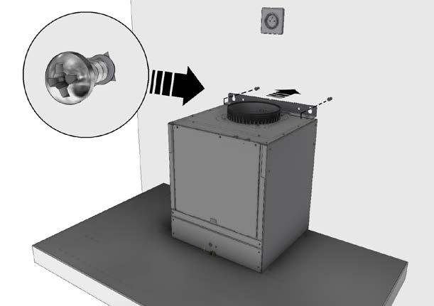
4 ALGEMENE INFORMATIE Algemeen Dit is de montage-instructie voor de op de voorzijde aangegeven Novy-afzuigkap. De gebruiksaanwijzing is een apart boekje dat ook bij deze afzuigkap is meegeleverd. Lees deze instructies goed door voor de installatie en ingebruikname van de wandschouwkap. Het is aan te bevelen om de installatie uitsluitend te laten uitvoeren door één of meerdere bevoegde personen. Neem de afzuigkap zorgvuldig uit de verpakking. De afzuigkap dient toegepast te worden boven een kookplaat en/of domino s en is uitsluitend bedoeld voor huishoudelijk gebruik. Belangrijk voordat u gaat monteren Op pagina 2 van deze montage-instructie vindt u de montagetekeningen. Voordat u gaat monteren, neem de volgende montagetips in acht: Voor het eenvoudiger monteren van de wandschouwkap wordt aangeraden dit met minimaal 2 personen uit te voeren. Controleer aan de hand van de tekening op pagina 2 of alle montagematerialen meegeleverd zijn. Positioneer het stopcontact zodanig dat deze achter de schachten van de wandschouw valt. Zorg dat het muur over voldoende draagkracht beschikt. De beschermfolie op het rvs kunt u voor montage verwijderen van de wandschouwkap of schachten. Pas op voor beschadigingen van het rvs. Afvoer of recirculatie Voordat u gaat monteren dient u de keuze te hebben gemaakt of u een afvoerkanaal naar buiten maakt of dat u de wandschouw als recirculatie afzuigkap gaat toepassen. Indien u kiest voor recirculatie biedt Novy de recirculatie kit aan met artikelnummer InTouch InTouch biedt de mogelijkheid om de Novy-afzuigkap te bedienen vanaf de Novy InTouch inductiekookplaat. Bij Novy kan een set besteld worden waardoor de afzuigkap direct reageert op de bediening van de kookplaat. Bij deze set wordt standaard een afstandsbediening geleverd. Kijk op de website voor de verschillende modellen van inductiekookplaten met InTouch. INSTALLATIE Volg de montage tekeningen op pagina Voorbereiding montage: Teken op de muur de verticale aslijn A van de schouwkap. De advieshoogte h tussen de onderkant van de schouwkap en de kookplaat is voor Advies montagehoogte met elektrische of keramische kookplaat (Hmin-Hmax)(mm): Montagehoogte met gas of inductie kookplaat (Hmin-Hmax)(mm): De waterpaslijn B wordt getekend op de gekozen hoogte van h mm. Plaats het stopcontact dichtbij de verticale aslijn A binnen de breedte van de schachten. De boormal bevindt zich in deze montage instructie. Plaats deze boormal op het kruispunt van de aslijn A en de waterpaslijn B en teken de 2 gaten af op de waterpaslijn. Boor met een 8mm boor de gaten in de muur Gebruik de grote pluggen (906055) en draai de bijbehorende grote schroeven (906143) gedeeltelijk in de muur. Let op, de schroeven nog niet helemaal indraaien! Hang de wandschouwkap met de beugel bovenop het motorhuis over deze schroeven. Positioneer de schouwkap C waterpas door de schroeven op de schouwkap zodanig te draaien zodat de schouwkap waterpas komt te hangen. Ook de hoogte van de schouwkap kan nog iets gesteld worden door de schroeven in en uit te draaien. Let op, de schroeven in de muur nog niet vast draaien! Open de onderplaat en neem het vetfilter uit de schouwkap. In de achterzijde van de schouwkap bevinden zich 2 gaten. Markeer deze gaten op de muur. Sluit de onderplaat en neem de wandschouwkap weer van de muur, om de gemarkeerde gaten op de muur te boren. Boor de gaten met een 6mm boor en gebruik de kleine pluggen (906115). Positioneer de schouwkap opnieuw tegen de muur. Controleer of alles nog waterpas hangt. Gebruik de kleine schroeven (906197) om de wandschouwkap goed tegen de muur te bevestigen. Draai nu ook de schroeven boven in de muur goed vast. NL 4
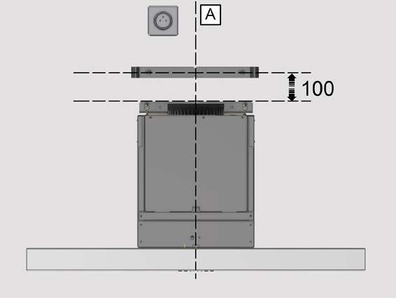
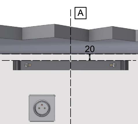
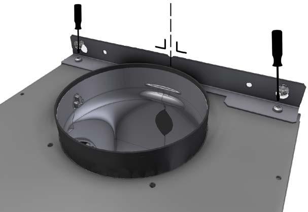
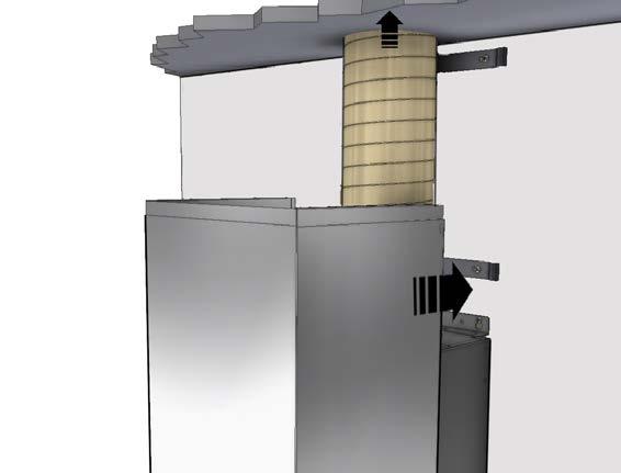
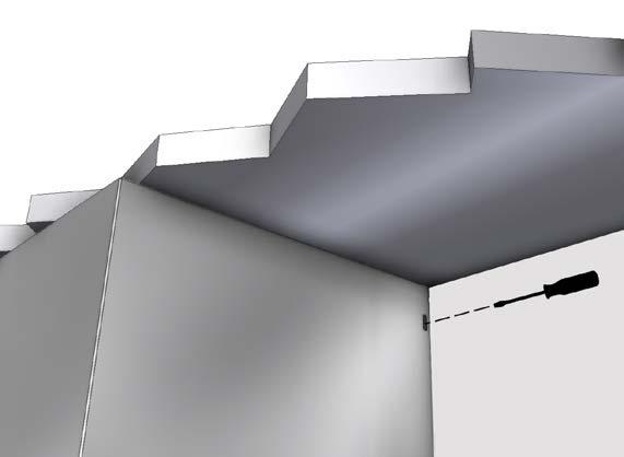
5 Installeer op de verticale aslijn de onderste afstandsbeugel, 100mm gemeten vanaf de bovenzijde van de montagebeugel tot het hart van het boorgat. Gebruik de pluggen (906115) en de schroeven (906197). Monteer de afstandsbeugel zodanig dat deze loodrecht en in het midden van de verticale aslijn op de muur komt. Monteer de bovenste afstandsbeugel op 20 mm gemeten vanaf het plafond tot bovenzijde van deze beugel. Zorg dat deze loodrecht en in het midden van de verticale aslijn gemonteerd wordt. Gebruik de pluggen (906115) en de schroeven (906197). Plaats de afvoerbuis op een aansluittuit van de motor m.b.v. aluminiumtape of met een slangklem. Plaats de stekker in het stopcontact. Neem de twee schachtdelen en plaats deze op de wandschouwkap. Let op dat dit voorzichtig gedaan wordt i.v.m. beschadigen van de schouwkap of de schachten. Klem de schachten om de onderste afstandshouder. Open de onderplaat en neem het filter uit de schouwkap. Schroef met de 4 schroeven (906151) de schacht van schouwkap vast van binnenuit. Trek het bovenste schachtdeel uit naar het plafond en klem deze achter de bovenste afstandshouder. Schroef daarna aan beide zijden de schacht vast aan de bovenste afstandsbeugel met de 2 meegeleverde rvs schroeven (906035). MONTAGE MOTORUNIT OP AFSTAND Bij de modellen 7605 en de 7615 wordt de motorunit op afstand van de afzuigkap gemonteerd. Er kan een keuze gemaakt worden tussen een binnenmotor, een gevelmotor voor buiten of een platdakmotor. Bij een gevelmotor dient de minimale afstand tussen de afzuigkap en de gevelmotor 5 meter te bedragen. De afzuigkap wordt op een stopcontact met randaarde aangesloten. De elektrische verbinding tussen de afzuigkap en de motorunit gebeurt door middel van een 6-polige stekerverbinding. Overige informatie vind u in de montage instructie van de betreffende motor. INSTALLATIE VAN HET AFVOERKANAAL Voor een optimale werking van de afzuigkap is het van belang om bij de installatie op de volgende punten te letten. Bij gebruik van een rond afvoerkanaal: Gebruik gladde, onbrandbare buizen met een inwendige diameter die gelijk is aan de uitwendige diameter van de aansluittuit van de afzuigkap. Voor de afzuigkap is een afvoerkanaal vereist van Ø150mm. Trek flexibele kanalen maximaal uit en snij deze op maat af. Verminder de afvoerdiameter niet. Dit zal de capaciteit doen verminderen en het geluidsniveau doen toenemen. Bij aansluiting op een kort afvoerkanaal kan het gewenst zijn in het kanaal een terugslagklep te monteren om windinval te voorkomen. Gebruik een slangklem of aluminiumtape voor luchtdichte verbindingen. Maak bij een afvoer door de buitengevel gebruik van het buitenmuurrooster. Bij gebruik van een plat afvoerkanaal: Gebruik platte kanalen met afgeronde hoeken en luchtgeleiders in de bochten. Deze kanalen zijn verkrijgbaar bij Novy. Algemeen: Maak het kanaal zo kort mogelijk en met zo min mogelijk bochten naar buiten. Vermijd haakse bochten. Maak gebruik van afgeronde bochten voor een goede luchtgeleiding. Bij een afvoer door de buitengevel, via een spouwmuur, dient er op gelet te worden dat het afvoerkanaal de spouw volledig overbrugt en iets afloopt naar de buitenzijde. Maak bij een afvoer via het dak gebruik van een dubbelwandige dakdoorvoer met voldoende doorlaat. Nooit aansluiten op een rookgasafvoerkanaal. Zorg voor voldoende luchttoevoer. Het aanvoeren van verse lucht kan geschieden door een raam of een buitendeur enigszins te openen of door een toevoerrooster aan te brengen. Voor een luchtdichte afsluiting gebruik de meegeleverde isolatieband ( ). ACCESSOIRES Recirculatie Indien u kiest voor recirculatie biedt Novy de recirculatiekit aan, type Deze kit bestaat uit een recirculatiebox welke achter de bovenschacht gemonteerd wordt en een Monoblock recirculatiefilter. Rugwandpaneel De rugwandpanelen zijn verkrijgbaar in de hoogten 690mm en 750mm. NL 5
6 Verlengkabel Bij het op afstand monteren van de motorunit kan het gewenst zijn een langere kabel tussen de afzuigkap en motor te plaatsen. De verlengkabel wordt gekoppeld aan de bestaande kabel. De verlengkabel heeft een lengte van 5 m. Venstercontact Deze afzuigkap is uitgerust met een aansluiting voor een venstercontactschakelaar. Indien de afzuigkap tegelijk moet werken met een verwarmingstoestel dat lucht uit het vertrek nodig heeft en als de vereiste toevoer van verse lucht enkel via een geopend venster kan gebeuren, is het mogelijk om op de afzuigkap een venstercontactschakelaar (niet bijgeleverd) aan te sluiten. De venstercontactschakelaar zorgt ervoor dat de afzuigkap alleen werkt indien het raam openstaat Als het venster gesloten is, kan de ventilator niet worden ingeschakeld. Als accessoire is een venstercontact kabel set verkrijgbaar (artikelnummer ). Overige accessoires - Slangklem instelbereik Ø mm Aluminium tape rol à 50 m Aluminium buitenmuurrooster voor Ø150 mm Mechanisch buitenmuurrooster Ø150 mm Terugslagklep Ø150 mm RVS cleaner: onderhoudsmiddel voor het reinigen van het RVS Wijzigingen en zet- of drukfouten voorbehouden, januari 2018 NL 6
7 INFORMATIONS GÉNÉRALES Généralités Il s agit de la notice de montage de la hotte Novy illustrée en page de couverture. Le mode d emploi consiste en un livret distinct fourni avec cette hotte. Lisez attentivement ces instructions avant d installer et de mettre en service la hotte à cheminée murale. Il est recommandé de confier l installation exclusivement à une ou plusieurs personnes compétentes. Retirez la hotte de son emballage avec précaution. La hotte doit être installée au-dessus d une table de cuisson et/ou de dominos. Elle est exclusivement à usage domestique. Important! Avant de commencer le montage Vous trouverez les dessins de montage en page 2 de cette notice de montage. Avant de commencer le montage, suivez les conseils de montage suivants : Pour faciliter le montage de la hotte, il est conseillé d y procéder avec 2 personnes. Vérifiez, en vous référant au dessin de la page 2, si tout le matériel a été livré. Positionnez la prise de courant de telle manière qu elle se trouve derrière les gaines de la cheminée murale. Assurez-vous que le mur possède une capacité portante suffisante. Vous pouvez, avant le montage, enlever le film de protection sur l acier inoxydable de la hotte à cheminée murale ou des gaines. Attention à ne pas endommager l acier inoxydable. Évacuation ou recyclage Avant de commencer le montage, vous devez avoir opté pour la réalisation d un conduit d évacuation vers l extérieur ou si vous allez utiliser la cheminée murale comme hotte à recyclage. Si vous optez pour le recyclage, Novy propose un kit de recyclage ( ). InTouch InTouch permet de commander la hotte Novy à partir de la table de cuisson à induction Novy InTouch. Novy propose un kit permettant à la hotte de réagir directement aux commandes de la table de cuisson. Ce kit est accompagné d une télécommande. Visitez le site web pour voir les différents modèles de table de cuisson à induction avec InTouch. INSTALLATION Suivez les dessins de montage en page Préparation du montage : Tracez sur le mur l axe vertical A de la hotte à cheminée. La hauteur «h» conseillée entre le bas de la hotte à cheminée et la table de cuisson est La hauteur de montage recommandée avec une table de cuisson électrique ou céramique est de 600 mm minimum et 750 mm maximum. La hauteur de montage avec une table de cuisson au gaz ou à induction est de 650 mm minimum et 750 mm maximum. La ligne horizontale B sera tracée à la hauteur «h» choisie mm. Placez la prise de courant près de l axe vertical A l intérieur de la largeur des gaines. Le gabarit de perçage se trouve dans cette notice de montage. Placez ce gabarit de perçage à l intersection de l axe A et de la ligne horizontale B et marquez les 2 trous sur la ligne horizontale. Percez les trous dans le mur à l aide d une mèche de 8 mm. Utilisez les grandes chevilles (906055) et vissez les grandes vis correspondantes (906143) partiellement dans le mur. Attention! Ne serrez pas les vis à fond! Accrocher la hotte à cheminée murale avec l étrier en dessus du boîtier du moteur par-dessus ces vis. Mettez la hotte à cheminée C en position horizontale en tournant les vis sur la hotte de manière ce que la hotte à cheminée se trouve accrochée en position parfaitement horizontale. De même, vous pouvez ajuster encore légèrement la hauteur de la hotte à cheminée en serrant et en desserrant les vis. Attention! Ne serrez pas encore les vis à fond dans le mur! Ouvrez la plaque de fond et retirez le filtre à graisse de la hotte à cheminée. L arrière de la hotte à cheminée comporte 2 trous. Marquez ces trous sur le mur. Fermez la plaque de fond et retirez la hotte du mur pour percer les trous marqués sur le mur. Percez les trous à l aide d une mèche de 6 mm et utilisez les petites chevilles (906115). Positionnez la hotte à cheminée à nouveau contre le mur. Vérifiez si l ensemble est encore accroché de manière parfaitement horizontale. Utilisez les petites vis (906197) pour bien fixer la hotte à cheminée murale contre le mur. Maintenant, serrez bien les vis du dessus dans le mur. FR 7
8 Installez l étrier d écartement inférieur sur l axe vertical à 100 mm mesurés entre le haut de l étrier de montage et l axe du trou percé. Utilisez les chevilles (906115) et les vis (906197). Montez l étrier d écartement de manière à ce qu il se retrouve d aplomb et au milieu de l axe vertical sur le mur. Montez l étrier d écartement supérieur à 20 mm, mesurés entre le plafond et le haut de cet étrier. Assurez-vous qu il est monté d aplomb et au milieu de l axe vertical. Utilisez les chevilles (906115) et les vis (906197). Placez le tube d évacuation sur un raccord du moteur à l aide de ruban adhésif aluminium ou d un collier de serrage. Insérer la fiche dans la prise de courant. Prenez les deux éléments de la gaine et placez-les sur la hotte à cheminée murale. Veillez à ce que cela soit fait avec précaution en raison du risque d endommagement de la hotte à cheminée ou des gaines. Serrez les gaines autour de l entretoise inférieure. Ouvrez la plaque de fond et retirez le filtre de la hotte à cheminée. À l aide des 4 vis (906151), serrez de l intérieur la gaine de la hotte à cheminée. Tirez l élément de gaine supérieur vers le plafond puis serrez-le derrière l entretoise supérieure. Puis serrez les deux côtés de la gaine contre l étrier d écartement supérieur à l aide des 2 vis en acier inoxydable fournies (906035). MONTAGE DU BLOC MOTEUR À DISTANCE Pour les modèles 7605 et 7615, le bloc moteur sera monté à distance de la hotte à cheminée. Vous pouvez choisir entre un moteur intérieur, un moteur pour façade pour montage extérieur et un moteur pour toit plat. Dans le cas d un moteur pour façade, la distance minimale entre la hotte et le moteur doit être de 5 mètres. La hotte sera raccordée à une prise mise à la terre. Le raccordement électrique entre la hotte et le bloc moteur sera effectué au moyen d un connecteur à 6 broches. Vous trouverez de plus amples informations dans la notice de montage du moteur en question. INSTALLATION DU CONDUIT D ÉVACUATION Pour un fonctionnement optimal de la hotte, il est important, lors de l installation, de respecter les consignes suivantes : Lors de l utilisation d un conduit d évacuation rond: Utilisez des tubes lisses et ignifuges dont le diamètre intérieur est égal au diamètre extérieur du raccord de la hotte. Etirez les conduits souples le plus possible puis découpez-les à dimension. Ne réduisez pas le diamètre de l évacuation. Tout rétréci entraine une diminution de l efficacité et une augmentation du niveau sonore. En cas de raccordement en toiture, il est nécessaire de mettre en place un antirefouleur pour stopper un retour d air froid en cuisine. Utilisez un collier de serrage ou de ruban adhésif aluminium pour rendre étanche les raccords. En cas d évacuation sur une façade extérieure, utilisez un clapet à volets mobiles. Lors de l utilisation d un conduit d évacuation plat: Utilisez des conduits plats aux angles arrondis équipés de conducteurs d air dans les coudes. Ces conduits sont disponibles chez Novy. Généralités: Faites en sorte que le conduit soit le plus court possible et le plus direct possible vers l extérieur. Évitez les coudes à 90. Réalisez des coudes ouverts pour un bon acheminement de l air. En cas d évacuation au travers d un mur à vide d air, assurez-vous que le conduit d évacuation le traverse et débouche à l extérieur. En cas d évacuation, utilisez un tubage à double paroi d une section suffisante. Ne raccordez jamais à un conduit de cheminée en service pour une autre fonction. Prévoyez impérativement une entrée d air suffisante dans la pièce. On peut assurer l apport d air frais avec une grille d aération ou une fenêtre ou une porte entrouverte. Pour assurer l étanchéité de l installation, utilisez le ruban d isolation blanc fourni. ACCESSOIRES Recyclage Si vous optez pour la recirculation, Novy propose le kit de recirculation réf Ce kit se compose d une boîte de recirculation qui se monte derrière la gaine supérieure et d un filtre de recirculation Monoblock. Prolongateur électrique En cas de montage à distance au-delà de 4m du bloc-moteur, un prolongateur électrique est nécessaire. Il a une longueur de 5m et sera couplé au câble existant. FR 8
9
10 BOORMAL 7600
11 260
12
13 Commutateur de fenêtre Cette hotte d aspiration est équipée d un raccord pour un interrupteur de contact de fenêtre. Si la hotte d aspiration doit fonctionner simultanément avec un chauffage extrayant l air de la pièce, et si l alimentation nécessaire en air frais doit se faire par le biais d une fenêtre ouverte, ce sera possible de raccorder la hotte d aspiration à l interrupteur de contact de la fenêtre (non inclus dans la livraison). Cet interrupteur empêche la hotte d aspiration de fonctionner quand la fenêtre n est pas ouverte ; le ventilateur ne pourra pas s enclencher quand la fenêtre est fermée. Un kit de câbles pour le contact de fenêtre (numéro de référence ) est dis ponible comme accessoire. Autres Accessoires - Collier de serrage ø 60 mm jusqu au 215 mm - Collier de serrage ø 60 mm jusqu au 135 mm - Adhésif Aluminium par 50 m - Clapet de façade clapet aluminium ø 150 mm - Clapet Antirefouleur ø 150 mm - Clapet Antirefouleur ø 125 mm Sous réserve de modifications et d erreurs de composition et d impression, Janvier 2018 FR 13
14 ALLGEMEINE INFORMATIONEN Allgemeine Informationen Dies ist die Montageanleitung für die auf der Vorderseite genannte Novy Dunstabzugshaube. Die Gebrauchsanleitung ist ein separates Heft, das ebenfalls im Lieferumfang dieser Dunstabzugshaube enthalten ist. Lesen Sie sich diese Anleitungen vor der Installation und Inbetriebnahme der Wand-Dunstabzugshaube sorgfältig durch. Es empfiehlt sich, die Installation ausschließlich durch eine oder mehrere autorisierte Person(en) durchführen zu lassen. Nehmen Sie die Dunstabzugshaube vorsichtig aus der Verpackung. Die Dunstabzugshaube ist für die Anbringung über Kochplatten und/oder Domino-Kochfeldern geeignet und ausschließlich für den Gebrauch im Haushalt vorgesehen. Wichtige vor der Montage zu beachtende Punkte Auf Seite 2 dieser Montageanleitung finden Sie die Montagezeichnungen. Bitte lesen Sie sich die folgenden Hinweise durch, bevor Sie mit der Montage beginnen: Die Wandhaube lässt sich einfacher montieren, wenn mindestens 2 Personen die Arbeiten durchführen. Kontrollieren Sie anhand der Zeichnung auf Seite 2, ob alle Befestigungsteile mitgeliefert wurden. Positionieren Sie die Steckdose so, dass sie hinter die Schächte der Wandhaube fällt. Stellen Sie sicher, dass die Tragfähigkeit der Wand ausreicht. Die Schutzfolie auf dem Edelstahl der Wandhaube oder Schächte können Sie vor der Montage entfernen. Achten Sie darauf, dass der Edelstahl nicht beschädigt wird. Abluft oder Umluft Bevor Sie mit der Montage beginnen, muss festgelegt werden, ob Sie einen Abluftkanal ins Freie legen oder die Wandhaube als Umluftgerät verwenden werden. Wenn Sie sich für die Umluftlösung entscheiden, bietet Novy ein passendes Umluftset ( ) an. InTouch InTouch bietet die Möglichkeit, die Novy-Dunstabzugshaube von der Novy InTouch Induktionskochplatte aus zu bedienen. Bei Novy kann ein Set bestellt werden, der dafür sorgt, dass die Dunstabzugshaube direkt auf die Bedienung der Kochplatte reagiert. Im Lieferumfang dieses Sets ist standardmäßig eine Fernbedienung enthalten. Auf der Website finden Sie verschiedene Induktionskochplatten-Modelle mit InTouch. INSTALLATION Befolgen Sie die Montagezeichnungen auf Seite Vorbereitung der Montage: Zeichnen Sie auf der Wand die vertikale Achsenlinie A der Wandhaube an. Die empfohlene Höhe h zwischen Unterseite der Wandhaube und der Kochfläche beträgt für Die empfohlene Montagehöhe bei einem Elektrro- oder Keramikkochfeld beträgt mindestens 600 mm und höchstens 750 mm. Die empfohlene Montagehöhe bei einem Gas- oder Induktionskochfeld beträgt mindestens 650 mm und höchstens 750 mm. Die horizontale Linie B wird auf der gewählten Höhe von h mm gezeichnet. Ordnen Sie die Steckdose nahe der vertikalen Achsenlinie A innerhalb der Breite der Schächte an. Die Bohrschablone befindet sich in dieser Montageanleitung. Halten Sie die Bohrschablone auf den Schnittpunkt der Achsenlinie A und der horizontalen Linie B und zeichnen Sie die beiden Löcher auf der horizontalen Linie an. Bohren Sie die Löcher mit einem 8-mm-Bohrer in die Wand. Verwenden Sie die großen Dübel (906055) und drehen Sie die zugehörigen großen Schrauben (906143) teilweise in die Wand. Achten Sie darauf, die Schrauben noch nicht vollständig festzudrehen! Hängen Sie Wandhaube mit dem Bügel oben auf dem Motorgehäuse über diese Schrauben. Positionieren Sie die Wandhaube C horizontal, indem Sie die Schrauben an der Wandhaube so verdrehen, dass die Wandhaube horizontal hängt. Auch die Höhe der Wandhaube kann etwas korrigiert werden, indem man die Schrauben hinein- oder herausdreht. Achten Sie darauf, die Schrauben in der Mauer noch nicht festzudrehen. Öffnen Sie die Unterseite und nehmen Sie den Fettfilter aus der Wandhaube heraus. In der Rückseite der Handhaube befinden sich 2 Löcher. Zeichnen Sie diese Löcher auf der Wand an. Schließen Sie die Unterseite und nehmen Sie die Wandhaube wieder von der Wand ab, um die angezeichneten Löcher in die Wand zu bohren. Bohren Sie die Löcher mit einem 6-mm-Bohrer und verwenden Sie die kleinen Dübel (906115). Positionieren Sie die Wandhaube wieder an der Wand. Kontrollieren Sie, ob alles horizontal ausgerichtet ist. Benutzen Sie die kleinen Schrauben (906197), um die Wandhaube sicher an der Wand zu befestigen. Drehen Sie jetzt auch die Schrauben in der Wand fest. DE 14
15 Installieren Sie auf der vertikalen Achsenlinie den unteren Abstandsbügel so, dass der Abstand von der Oberseite des Montagebügels zur Mitte des Bohrlochs 100 mm beträgt. Benutzen Sie die Dübel (906115) und die Schrauben (906197). Montieren Sie den Abstandsbügel so, dass er senkrecht und in der Mitte der vertikalen Achsenlinie auf der Wand sitzt. Montieren Sie den oberen Abstandsbügel in einem Abstand von 20 mm gemessen von der Decke zur Oberseite dieses Bügels. Achten Sie darauf, dass er senkrecht und in der Mitte der vertikalen Achsenlinie montiert wird. Benutzen Sie die Dübel (906115) und die Schrauben (906197). Setzen Sie das Abluftrohr unter Verwendung von Aluminium-Klebeband oder einer Schlauchklemme auf eine Anschlusstülle des Motors auf. Stecken Sie den Stecker in die Steckdose. Nehmen Sie die zwei Schachtteile und setzen Sie sie auf die Wandhaube auf. Gehen Sie dabei vorsichtig vor, damit die Wandhaube oder die Schächte nicht beschädigt werden. Klemmen Sie die Schächte um den unteren Abstandshalter. Öffnen Sie die Unterseite und nehmen Sie den Filter aus der Wandhaube heraus. Schrauben Sie den Schacht der Wandhaube mit den 4 Schrauben (906151) von innen fest. Ziehen Sie den oberen Schachtteil zur Decke hin heraus und klemmen Sie ihn hinter den oberen Abstandshalter. Schrauben Sie den Schacht danach auf beiden Seiten mit den 2 mitgelieferten Edelstahlschrauben (906035) an dem oberen Abstandsbügel fest. SEPARATE MONTAGE DER MOTOREINHEIT Bei den Modellen 7605 und 7615 wird die Motoreinheit separat von der Wandhaube montiert. Es kann zwischen einem Innenmotor, einem Fassadenmotor für die Außenmontage und einem Flachdachmotor gewählt werden. Bei einem Fassadenmotor muss der Abstand zwischen der Dunstabzugshaube und dem Fassadenmotor mindestens 5 Meter betragen. Die Dunstabzugshaube wird an eine Steckdose mit Schutzerdung angeschlossen. Die elektrische Verbindung zwischen der Dunstabzugshaube und der Motoreinheit erfolgt mithilfe eines 6-poligen Steckverbinders. Weitere Informationen finden Sie in der Montageanleitung für den betreffenden Motor. INSTALLATION DES ABLUFTKANALS Die Ableitung der Abluft von der Dunstabzugshaube muss korrekt gelöst werden. Für eine optimale Funktion der Dunstabzugshaube ist es wichtig, dass bei der Installation die folgenden Punkte beachtet werden: Verwenden Sie glatte, nicht brennbare Rohre, deren Innendurchmesser dem Außendurchmesser von der Anschlusstülle der Dunstabzugshaube entspricht. Ziehen Sie die flexiblen Kanäle maximal straff und schneiden Sie sie auf Länge ab. Verringern Sie nicht den Durchmesser des Abluftkanals. Hierdurch würde sich die Kapazität verringern und der Lärmpegel entsprechend zunehmen. Machen Sie den Kanal so kurz wie möglich und führen Sie die Abluft mit möglichst wenig Kurven nach draußen. Vermeiden Sie rechtwinklige Kurven. Nutzen Sie abgerundete Kurven, damit die Luftströmung möglichst nicht behindert wird. Flacher Kanal: Die Oberfläche des flachen Kanals muss gleich groß sein Ø150 mm = 177 cm². Bei Ableitung über eine Hohlwand durch die Außenfassade ist darauf zu achten, dass der Abluftkanal die Hohlwand vollständig überbrückt und mit leichtem Abwärtsgefälle nach außen verlegt wird. Bei Anschluss an einen kurzen Abluftkanal kann es wünschenswert sein, in dem Kanal ein Rückschlagklappe zu montieren, um Windeinfall zu verhindern. Benutzen Sie eine Schlauchklemme oder ein Aluminium-Klebeband zur Herstellung von luftdichten Verbindungen. Verwenden Sie bei einer Ableitung durch die Außenfassade das Außenmauergitter. Verwenden Sie bei einer Ableitung über das Dach eine doppelwandige Dachdurchführung mit ausreichendem Durchlass. Niemals an einen Kanal zur Ableitung von Rauchgas anschließen. Für ausreichende Luftzufuhr sorgen. Die Zuführung von Frischluft kann erfolgen, indem man ein Fenster oder eine Außentür etwas öffnet oder ein Zuluftgitter anbringt. Fensterschaltung Diese Dunstabzugshaube ist mit einem Anschluss für einen Fensterkontaktschalter ausgestattet. Wenn die Dunstabzugshaube gleichzeitig mit einer Feu erstelle (Ofen, Kamin etc.) betrieben wird die Luft aus dem Raum benötigt, und wenn die erforderliche Frischluftzufuhr nur durch ein geöffnetes Fenster er folgen kann, muss ein Fensterkontaktschalter (nicht mitgeliefert) an die Dunstabzugshaube angeschlos sen werden. Dadurch wird sichergestellt, dass die Dunstabzugshaube nur eingeschaltet werden kann, wenn das Fenster geöffnet ist. Bei geschlossenem Fenster kann der Dunstabzug dann nicht einge schaltet werden. DerFensterkontakt-Kabelsatz (Arti kelnummer ) ist als Zubehör erhältlich. Änderungen und Satz- oder Druckfehler vorbehalten, Januar 2018 DE 15
16 GENERAL INFORMATION General These are the mounting instructions for the Novy hood shown on the cover. The manual is a separate booklet that has been supplied with this hood. Carefully read these instructions before installing and commissioning the wall-mounted chimney hood. It is recommended to have one or more qualified persons carry out the installation only. Carefully take the hood from the packaging. The hood is to be used above a cooking plate and/or domino and intended for household use only. Important before mounting Page 2 of these mounting instructions show the mounting drawings. Observe the following mounting tips before starting the mounting activities: For easier mounting of the wall-mounted chimney hood, it is recommended to do this with at least 2 persons. Check if all mounting materials have been supplied using the drawing on page 2. Position the wall socket such, that it is behind the shafts of the wall-mounted chimney hood. Make sure that the wall has sufficient load bearing capacity. You can remove the protective film on the stainless steel of the wall-mounted chimney hood or shafts. Avoid damaging the stainless steel. Exhaust or recirculation Before starting any mounting activities, you must have made the choice if you are going to make an exhaust duct to the outside or if you are going to use the wall-mounted chimney hood as a recirculation hood. If you choose for recirculation, Novy offers the recirculation kit ( ). InTouch InTouch offers you the possibility to control the Novy cooker hood from the Novy InTouch induction cooking plate. A set can be ordered from Novy which makes the cooker hood react directly to the operation of the cooking plate. This set by default includes a remote control. Visit the website for the different models of induction cooking plates with InTouch. INSTALLATION Follow with mounting drawings on page Preparations for mounting: Draw the vertical axis A of the chimney hood on the wall. The recommended height h between the bottom of the chimney hood and the cooking plate is for The recommended mounting height for an electrical or ceramic cooking plate is min. 600 mm and max. 750 mm. The mounting height for a gas or induction cooking plate is min. 650 mm and max. 750 mm. The level line B is drawn at the chosen height of h mm. Install the wall socket near the vertical axis A within the shaft widths. The drilling jig is to be found in these mounting instructions. Place this drilling jig on the crossing point of the axis A and the level line B and draw the 2 holes on the level line. Drill holes in the wall using an 8 mm drill. Use the large plugs (906055) and partly screw the accompanying large screws (906143) into the wall. Attention: do not fully screw in the screws yet! Hang the wall-mounted chimney hood with the bracket on top of the motor housing over these screws. Level the chimney hood C by turning the screws on the chimney hood such, that the chimney hood is hanging level. The height of the chimney hood can slightly be adjusted by screwing the screws in and out. Attention: do not tighten the screws in the wall yet! Open the bottom plate and remove the fat filter from the chimney hood. There are 2 holes on the rear side of the chimney hood. Mark these holes on the wall. Close the bottom plate and take the chimney hood off the wall in order to be able to drill the marked holes. Drill the holes with a 6 mm drill and use the small plugs (906115). Position the chimney hood against the wall again. Check if the hood is still hanging level. Use the small screws (906197) to properly attach the wall-mounted chimney hood to the wall. Now also tighten the screws above in the wall. Install the lower spacer bracket on the vertical axis 100 mm from the upper side of the mounting bracket to the centre of the drilled hole. Use the plugs (906115) and the screws (906197). Mount the spacer bracket such, that it is perpendicular to and in the centre of the vertical axis on the wall. Mount the upper spacer bracket at 20 mm between the ceiling and the top of the bracket. Make sure that the spacer bracket is mounted perpendicular to and in the centre of the vertical axis. Use the plugs (906115) and the screws (906197). EN 16
17 9 10 Place the exhaust pipe on a connection nozzle of the motor using aluminium tape or a hose clamp. Put the plug into the wall socket. Take the two shaft parts and place them onto the wall-mounted chimney hood. Make sure that this is done carefully in order to prevent the chimney hood or the shafts from being damaged. Clamp the shafts around the lower spacer. Open the bottom plate and remove the filter from the chimney hood. Tighten the shaft of the chimney hood with the 4 screws (906151) from the inside. Pull out the upper shaft part towards the ceiling and clamp it behind the upper spacer. Then fasten the shaft on both sides onto the upper spacer bracket using the 2 supplied stainless steel screws (906035). MOUNT THE REMOTE MOTOR UNIT For the models 7605 and 7615 the remote motor unit of the chimney hood is mounted. A choice can be made between an internal motor, an external motor for outside mounting or a roof motor. With an external motor the minimum distance between the hood and the external motor must be 5 metres. The hood is connected to an earthed wall socket. The hood and the motor unit are electrically connected by means of a 6-pole plug connection. Additional information can be found in the mounting instructions of the motor involved. INSTALL THE EXHAUST DUCT The exhaust of the hood must be properly taken care of. For optimum performance of the hood it is important to pay attention to the following items during the installation: Use smooth, non-flammable pipes with an internal diameter that is equal to the external diameter of the connection nozzle of the hood. Maximally extend flexible ducts and cut them to size. Do not reduce the exhaust diameter. This will lower the capacity and raise the noise level. Make the duct as short as possible and with as few as possible bends to the outside. Avoid square bends. Use rounded bends for proper air conduction. Flat duct: the surface of a flat duct must be the same size as Ø150 mm = 177 cm². In case of an exhaust pipe through the outside wall passing a cavity wall, make sure that the exhaust duct fully bridges the cavity and slightly declines to the outside. When connecting to a short exhaust duct, it may be required to mount a non-return valve in the duct to avoid wind blowing in. Use a hose clamp or aluminium tape for airtight connections. In case of an exhaust pipe through the roof, use a double-walled roof passage with sufficient width. Never connect to a flue duct. Make sure that sufficient air is supplied. Fresh air can be supplied by slightly opening a window or an outside door or by installing an inlet grate. ACCESSORIES Recirculation If you choose for recirculation, Novy offers the recirculation kit, type This kit includes a recirculation box that is mounted behind the upper shaft and a Monoblock recirculation filter. Extension cable When mounting the motor unit remotely, it may be desirable to mount a longer cable between the cookerhood and the motor. The extension cable is connected to the existing cable. The extension cable has a length of 5m. Window switch This hood is equipped with a connection for a con tact window switch. If the hood is to work simultane ously with a heating appliance that pulls air from the room, and if the required supply of fresh air can only be through an open window, it is possible to connect a window contact switch (not supplied) to the hood. This ensures the hood only works if the window is open. When the window is closed, the fan can not be turned on. A window contact cable set is available as an accessory (part number ). Characteristics of the product on condition of changes or printing errors, january 2018 EN 17
18
19
20 NOVY nv behoudt zich het recht voor te allen tijde en zonder voorbehoud de constructie en de prijzen van haar producten te wijzigen. NOVY SA se réserve le droit de modifier en tout temps et sans préavis la construction et les prix de ses produits. NOVY nv behält sich das Recht vor, jederzeit und ohne Vorbehalt die Konstruktion und die Preise seiner Produkte zu ändern. Novy nv reserves the right at any time and without reservation to change the structure and the prices of its products. NOVY nv Noordlaan 6 B KUURNE Tel. 056/ Fax 056/ novy@novy.be France: Tél: Deutschland und Österreich: Tel: +49 (0) Nederland: Tel.: +31 (0) España: Tel.: Italia: Tel.:
NL - België Installatievoorschriften p. 3 Nederland. FR - Belgique Instructions d installation p. 5 France
 NL - België Installatievoorschriften p. 3 Nederland FR - Belgique Instructions d installation p. 5 France DE - Belgien Montageanleitung p. 11 Deutschland 7241/15-7251/15-7490/15 7246/15-7256/15-7495/15
NL - België Installatievoorschriften p. 3 Nederland. FR - Belgique Instructions d installation p. 6 France
 NL - België Installatievoorschriften p. 3 Nederland FR - Belgique Instructions d installation p. 6 France DE - Belgien Montageanleitung p. 8 Deutschland Österreich Schweiz 7211/15-7221/15-7470/15 7216/15-7226/15-7475/15
NL - België Installatievoorschriften p. 3 Nederland. FR - Belgique Instructions d installation p. 5 France
 NL - België Installatievoorschriften p. 3 Nederland FR - Belgique Instructions d installation p. 5 France EN Operating and installation Instructions p. 11 DE - Belgien Montageanleitung p. 13 Deutschland
NL - België Installatievoorschriften p. 3 Nederland. FR - France Instructions d installation p. 5 Belgique Suisse
 NL - België Installatievoorschriften p. 3 Nederland FR - France Instructions d installation p. 5 Belgique Suisse DE - Deutschland Montageanleitung p. 7 Belgien Österreich Schweiz 7800/16-7805/16 5 6 6
NL Installatievoorschriften p. 4. FR Instructions d installation p. 6. DE Montageanleitung p. 8. EN Operating and installation instructions p.
 NL Installatievoorschriften p. 4 FR Instructions d installation p. 6 DE Montageanleitung p. 8 EN Operating and installation instructions p. 11 7830/1-7831/1 7840/1-7841/1 1 3 2 4 5 6 7 8 9 10 ALGEMENE
NL Installatievoorschriften p. 3. FR Instructions d installation p. 5
 NL Installatievoorschriften p. 3 FR Instructions d installation p. 5 6202 1 5 2 6 3 7 4 8 ALGEMENE INFORMATIE Algemeen Dit is de montage-instructie voor de op de voorzijde aangegeven Novy-afzuigkap. De
NL - België Installatievoorschriften p. 3 Nederland Installatievoorschriften. FR - France Instructions d installation p.
 NL - België Installatievoorschriften p. 3 Nederland Installatievoorschriften FR - France Instructions d installation p. 4 Belgique Suisse DE - Deutschland Montageanleitung p. 5 Belgien Österreich Schweiz
NL - België Installatievoorschriften p. 3 Nederland. FR - Belgique Instructions d installation p. 5 France
 NL - België Installatievoorschriften p. 3 Nederland FR - Belgique Instructions d installation p. 5 France EN Operating and installation Instructions p. 11 DE - Belgien Montageanleitung p. 13 Deutschland
NL - België Installatievoorschriften p. 3 Nederland. FR - Belgique Instructions d installation p. 5 France
 NL - België Installatievoorschriften p. 3 Nederland FR - Belgique Instructions d installation p. 5 France DE - Belgien Montageanleitung p. 11 Deutschland 7241/15-7251/15-7490/15 7246/15-7256/15-7495/15
NL Installatievoorschriften p. 3. FR Instructions d installation p. 6. DE Montageanleitung p. 9. EN Installation instructions p.
 NL Installatievoorschriften p. 3 FR Instructions d installation p. 6 DE Montageanleitung p. 9 EN Installation instructions p. 12 810/16-811/16 820/16-821/16 810/811 820/821 1 x 609014 1 x 801006 1 x 7400020
NL - België Installatievoorschriften p. 3 Nederland. FR - Belgique Instructions d installation p. 6 France
 NL - België Installatievoorschriften p. 3 Nederland FR - Belgique Instructions d installation p. 6 France DE - Belgien Montageanleitung p. 8 Deutschland 7300/15-7305/15 6 15x 906055 3 x 140009 15x 906143
NL - België Installatievoorschriften p. 3 Nederland. FR - Belgique Instructions d installation p. 6 France
 NL - België Installatievoorschriften p. 3 Nederland FR - Belgique Instructions d installation p. 6 France DE - Belgien Montageanleitung p. 8 Deutschland 7300/15-7305/15 7300-15 Montage NL-FR-DE.indd 1
NL - België Installatievoorschriften p. 3 Nederland. FR - Belgique Instructions d installation p. 6 France
 NL - België Installatievoorschriften p. 3 Nederland FR - Belgique Instructions d installation p. 6 France DE - Belgien Montageanleitung p. 8 Deutschland Österreich Schweiz 7211/15-7221/15-7470/15 7216/15-7226/15-7475/15
NL Installatievoorschriften p. 3. FR Instructions d installation p. 5. DE Montageanleitung p. 6. EN Operating and installation Instructions p.
 NL Installatievoorschriften p. 3 FR Instructions d installation p. 5 DE Montageanleitung p. 6 EN Operating and installation Instructions p. 8 7550 1 2 3 4 5 6 7 ALGEMENE INFORMATIE Algemeen Dit is de montage-instructie
NL Installatievoorschriften p. 4. FR Instructions d installation p. 6. DE Montageanleitung p. 9. EN Operating and installation Instructions p.
 NL Installatievoorschriften p. 4 FR Instructions d installation p. 6 DE Montageanleitung p. 9 EN Operating and installation Instructions p. 11 230 230_10509_MA1 2x 230.020 1 4x 230.055 1x 990.165 1x 990.271
NL - België Installatievoorschriften p. 3 Nederland. FR - Belgique Instructions d installation p. 6 France
 NL - België Installatievoorschriften p. 3 Nederland FR - Belgique Instructions d installation p. 6 France UK - United Kingdom Installation instructions p. 8 United Kingdom DE - Belgien Montageanleitung
NL Installatievoorschriften p. 4. FR Instructions d installation p. 6. DE Montageanleitung p. 8. EN Operating and installation instructions p.
 NL Installatievoorschriften p. 4 FR Instructions d installation p. 6 DE Montageanleitung p. 8 EN Operating and installation instructions p. 11 7830/1-7831/1 7840/1-7841/1 1 3 2 4 5 6 7 8 9 10 ALGEMENE
Montage-instructie Instruction manual Montage-Anleitung. Doorkeeper
 Montage-instructie Instruction manual Montage-Anleitung Doorkeeper NEDERLANDS Montage INTERSTEEL Doorkeeper 1. De geadviseerde montagehoogte is ca. 145 cm. Teken deze af op uw kozijn. 2. Gebruik de bijgeleverde
NL - België Installatievoorschriften p. 3 Nederland. FR - Belgique Instructions d installation p. 5 France Suisse
 NL - België Installatievoorschriften p. 3 Nederland FR - Belgique Instructions d installation p. 5 France Suisse DE - Belgien Montageanleitung p. 7 Deutschland Österreich Schweiz EN Operating and installation
NL - België Installatievoorschriften p. 3 Nederland. FR - Belgique Instructions d installation p. 8 France
 NL - België Installatievoorschriften p. 3 Nederland FR - Belgique Instructions d installation p. 8 France DE - Belgien Montageanleitung p. 14 Deutschland Österreich Schweiz EN Operating and installation
Vision NL Installatievoorschriften p. 4. FR Instructions d installation p. 7. DE Montageanleitung S. 10
 NL Installatievoorschriften p. 4 FR Instructions d installation p. 7 DE Montageanleitung S. 10 EN Operating and installation Instructions p. 13 Vision 7835 7835_10519_V01_MA1 1 3 2 4 5 A B C D 6 7 8 9
NL - België Installatievoorschriften p. 4 Nederland. FR - France Instructions d installation p. 6 Belgique Suisse
 NL - België Installatievoorschriften p. 4 Nederland FR - France Instructions d installation p. 6 Belgique Suisse DE - Deutschland Montageanleitung p. 8 Belgien Österreich Schweiz 661/15-662/15-663/15 691/15-692/15-693/15
GB - Installation manual Mercedes Benz C-Class A205 convertible wind deflector (from 2015).
.") GB - Installation manual Mercedes Benz C-Class A205 convertible wind deflector (from 2015). DE Montage Anleitung Mercedes Benz C-Klasse Cabrio Windschott (ab 2015). NL Montage handleiding Mercedes Benz
GB - Installation manual Mercedes Benz C-Class A205 convertible wind deflector (from 2015). DE Montage Anleitung Mercedes Benz C-Klasse Cabrio Windschott (ab 2015). NL Montage handleiding Mercedes Benz
NL - België Installatievoorschriften p. 3. FR - Belgique Instructions d installation p. 5 France. EN Operating and installation Instructions p.
 NL - België Installatievoorschriften p. 3 FR - Belgique Instructions d installation p. 5 France EN Operating and installation Instructions p. 7 DE - Belgien Montageanleitung p. 9 Deutschland Österreich
OUTDOOR HD BULLET IP CAMERA PRODUCT MANUAL
 OUTDOOR HD BULLET IP CAMERA PRODUCT MANUAL GB - NL GB PARTS & FUNCTIONS 1. 7. ---- 3. ---- 4. ---------- 6. 5. 2. ---- 1. Outdoor IP camera unit 2. Antenna 3. Mounting bracket 4. Network connection 5.
Plaatsingsvoorschriften Govawall Instructions de montage Govawall Verlegeanleitung Govawall Installation instructions Govawall
 V s u stainable p r i va c y NL F D UK Plaatsingsvoorschriften Govawall Instructions de montage Govawall Verlegeanleitung Govawall Installation instructions Govawall - + 502 40 502 6 x Ø 6 mm 2590 502
NL - België Installatievoorschriften p. 4 Nederland. FR - Belgique Instructions d installation p. 6 France
 NL - België Installatievoorschriften p. 4 Nederland FR - Belgique Instructions d installation p. 6 France DE - Belgien Montageanleitung p. 8 Deutschland 7810400 7810.400-C Montage NL-FR-DE.indd 1 23/06/14
Installatievoorschriften Motor op afstand buiten Instructions d installation Moteur dissocié extérieur Montageanleitung Externes Motor Außenwand
 44999/1 Installatievoorschriften Motor op afstand buiten Instructions d installation Moteur dissocié extérieur Montageanleitung Externes Motor Außenwand 4 x 90606 x 90604 1 x 906292 1 x 71011 1 x 906287
NL - België Installatievoorschriften p. 3 Nederland. FR - Belgique Instructions d installation p. 5 France
 NL - België Installatievoorschriften p. 3 Nederland FR - Belgique Instructions d installation p. 5 France DE - Belgien Montageanleitung p. 7 Deutschland 7800/15-7805/15 7800-15 Montage NL-FR-DE-EN.indd
7456/11-7465/11-7466/11-7245/12-7246/12-7255/12-7256/12-7495/11
 NL - België Installatievoorschriften p. 3 FR - Belgique Instructions d installation p. 6 France DE - Belgien Montageanleitung p. 7 Deutschland NL - Nederland Installatievoorschriften p. 8 7450/11-7451/11-7460/11-7461/11-7240/12-7241/12-7250/12-7251/12-7490/11-7455/11
NL - België Installatievoorschriften p. 3. FR - Belgique Instructions d installation p. 5 France. EN Operating and installation Instructions p.
 NL - België Installatievoorschriften p. 3 FR - Belgique Instructions d installation p. 5 France EN Operating and installation Instructions p. 7 DE - Belgien Montageanleitung p. 13 Deutschland Österreich
1/8 ATLAS Atlas cabinet cabinet 1 7
 TLS cabinet / / / 0 D E F G H / L x Lx x L / x x D E Dx Ex / x x x x x x Fx x Hx Gx Fx Fx Fx Fx G H G H H G 0 0 0 0 0 / L / 0 NL: Deze kast bevat twee gaten aan de achterkant om aan de wand te kunnen bevestigen.
NL - België Installatievoorschriften p. 3 Nederland. FR - Belgique Instructions d installation p. 4 France
 NL - België Installatievoorschriften p. 3 Nederland FR - Belgique Instructions d installation p. 4 France DE - Belgien Montageanleitung p. 5 Deutschland Österreich Schweiz 810/15-811/15 820/15-821/15 810/811
NL - België Installatievoorschriften p. 3 Nederland. FR - Belgique Instructions d installation p. 4 France Suisse
 NL - België Installatievoorschriften p. 3 Nederland FR - Belgique Instructions d installation p. 4 France Suisse DE - Belgien Montageanleitung p. 5 Deutschland Schweiz 855/7-856/7 1 4 x 830018 16 x 906151
Rhythm of Light. Susanne de Graef, Montagehandleiding / Instruction manual
 Rhythm of Light Susanne de Graef, 2016 Montagehandleiding / Instruction manual GELEVERD MATERIAAL / SUPPLIED MATERIAL B. C. D. A. E. F. A. B. C. D. E. F. armatuur / fixture fitting lange staalkabels (3)
DE Wippadapter für Jung-Serien Seite 2 EN Rocker adapter for Jung series Page 3. Adaptateur à bascule pour les séries Jung. Page 4
 DE Wippadapter für Jung-Serien Seite 2 EN Rocker adapter for Jung series Page 3 FR Adaptateur à bascule pour les séries Jung Page 4 NL Schakelaaradapter voor Jung-series Pagina 5 DE Funktion Die Wippadapter
NL - België Installatievoorschriften p. 3. FR - Belgique Instructions d installation p. 4 France. DE - Belgien Montageanleitung p.
 NL - België Installatievoorschriften p. FR - Belgique Instructions d installation p. France DE - Belgien Montageanleitung p. Deutschland NL - Nederland Installatievoorschriften p. 6 00/ - 0/ 6 x 060 x
NL - België Installatievoorschriften p. 3 Nederland. FR - Belgique Instructions d installation p. 5 France
 NL - België Installatievoorschriften p. 3 Nederland FR - Belgique Instructions d installation p. 5 France DE - Belgien Montageanleitung p. 7 Deutschland Österreich Schweiz EN Operating and installation
NL - België Installatievoorschriften p. 3. FR - Belgique Instructions d installation p. 4 France. NL - Nederland Installatievoorschriften p. 5 245.
 NL - België Installatievoorschriften p. FR - Belgique Instructions d installation p. 4 France NL - Nederland Installatievoorschriften p. 5 45.999 4 x 8008 8 x 90605 x 80006 x 80 6 x 9069 4 x 906055 + 9064
CONTENU DU CARTON CGI DÉTAIL DU SACHET VISSERIE
 F Page Les informations contenues dans ce manuel vont vous permettre de procéder au montage et à l utilisation du produit, en toute sécurité pour vous et votre entourage. Vous devez prendre connaissance
OUTDOOR HD DOME IP CAMERA PRODUCT MANUAL GB - NL
 OUTDOOR HD DOME IP CAMERA PRODUCT MANUAL GB - NL GB PARTS & FUNCTIONS 2. ---- 1. ---- 3. ---- 7. ---------- 5. 4. 6. 1. Outdoor IP camera unit 2. Antenna 3. Mounting bracket 4. Network connection 5. Power
NL - België Installatievoorschriften p. 4 Nederland. FR - Belgique Instructions d installation p. 6 France
 NL - België Installatievoorschriften p. 4 Nederland FR - Belgique Instructions d installation p. 6 France DE - Belgien Montageanleitung p. 8 Deutschland Österreich Schweiz 663/5 693/5 4 1 5 2 6 3 7 2 8
NL - België Installatievoorschriften p. 3 Nederland. FR - Belgique Instructions d installation p. 5 France
 NL - België Installatievoorschriften p. 3 Nederland FR - Belgique Instructions d installation p. 5 France DE - Belgien Montageanleitung p. 7 Deutschland Österreich Schweiz EN Operating and installation
Fusion NL Installatievoorschriften p. 3. FR Instructions d installation p. 5. DE Montageanleitung S. 7. EN Installation instructions p.
 NL Installatievoorschriften p. 3 FR Instructions d installation p. 5 DE Montageanleitung S. 7 EN Installation instructions p. 9 Fusion 680-686 680_10527_MA1 1 2 3 4 5 2 ALGEMENE INFORMATIE Algemeen Dit
45MM 385X565CM GARAGE SDPAU+EDC (ART 4004M)
") 45MM 385X565CM GARAGE SDPAU+EDC (ART 4004M) Onderdelenlijst Liste d'inventaire 4004M Wandelementen / Eléments des parois Typ ovoïde 45mm 385x565 SDPAU Artikel nr Afmeting / Dimension # Functie/Fonction
45MM 385X565CM GARAGE SDPAU+EDC (ART 4004M) Onderdelenlijst Liste d'inventaire 4004M Wandelementen / Eléments des parois Typ ovoïde 45mm 385x565 SDPAU Artikel nr Afmeting / Dimension # Functie/Fonction
NL - België Installatievoorschriften p. 5. FR - Belgique Instructions d installation p. 7 France. EN Operating and installation Instructions p.
 NL - België Installatievoorschriften p. 5 FR - Belgique Instructions d installation p. 7 France EN Operating and installation Instructions p. 9 DE - Belgien Montageanleitung p. 11 Deutschland Österreich
NL - België Installatievoorschriften p. 3 Nederland. FR - Belgique Instructions d installation p. 5 France Suisse
 NL - België Installatievoorschriften p. 3 Nederland FR - Belgique Instructions d installation p. 5 France Suisse DE - Belgien Montageanleitung p. 7 Deutschland Schweiz EN - Installation Instructions p.
heatwave small OK! Onderdelen - Parts - Teile Ø 8 mm Ø 10 mm p q Montagehandleiding - Instructions de montage Montageanleiting - Mounting instructions
 heatwave small Montagehandleiding - Instructions de montage Montageanleiting - Mounting instructions Het is mogelijk de Heatwave over een volledig bereik van 360 te monteren. 778 mm Il est ossible de monter
Flybye. Ernst Koning, Montagehandleiding / Instruction manual
 Flybye Ernst Koning, 2018 Montagehandleiding / Instruction manual GELEVERD MATERIAAL / MATERIALS SUPPLIED A. B. C. D. E. F. G. A. B. C. D. E. F. G. H. H. lichtbuis / lighting tube plafondkap / ceiling
COLD/FREEZER ROOM. Gebruikershandleiding. Gebrauchsanweisung Owners manual Le mode d emploi
 COLD/FREEZER ROOM Gebruikershandleiding Gebrauchsanweisung Owners manual Le mode d emploi 1 CONTENT 1 Assembly of the cold rooms Kühlraum montage Assemblage des chambres froid Montage van de koelcel...
NL Installatievoorschriften p. 4. FR Instructions d installation p. 8. DE Montageanleitung p. 11. EN Operating and installation Instructions p.
 NL Installatievoorschriften p. 4 FR Instructions d installation p. 8 DE Montageanleitung p. 11 EN Operating and installation Instructions p. 15 828/1 829/1 MA828 V06 Montage NL-FR-DE-EN.indd 1 18/08/16
FSW-VW-2X2 FSW-VW. Handleiding / Manual
 FSW-VW-2X2 FSW-VW Handleiding / Manual Rev. 1.0 17-03-2014 I Pakketinhoud / Content Accessoires Benodigde gereedschappen / Required Tools Montage / Assembling Onderhoud / Maintenance Veel Gestelde Vragen
NL - België Installatievoorschriften p. 3. FR - Belgique Instructions d installation p. 5 France. EN Operating and installation Instructions p.
 NL - België Installatievoorschriften p. 3 FR - Belgique Instructions d installation p. 5 France EN Operating and installation Instructions p. 7 DE - Belgien Montageanleitung p. 13 Deutschland NL - Nederland
Bullerjan B 4 Stahl, Keramik und Keramik+
 Bullerjan B 4 Stahl, Keramik und Keramik+ Anleitung zur Montage der Tür für die Holzbox Instruction for the mounting of the door for wood storage box Instructions pour le montage de la porte de la boîte
NL - België Installatievoorschriften p. 4 Nederland. FR - Belgique Instructions d installation p. 6 France
 NL - België Installatievoorschriften p. 4 Nederland FR - Belgique Instructions d installation p. 6 France DE - Belgien Montageanleitung p. 8 Deutschland Österreich Schweiz EN Operating and installation
34MM BODEN 355X535+30 CM SDPAU+EDC
 34MM BODEN 355X535+30 CM SDPAU+EDC Onderdelenlijst Liste d'inventaire 6005 Wandelementen / Eléments des parois Typ Ovoïde 34mm 355x535+30 SDPAU+EDC01L Artikel nr Afmeting / Dimension # Functie/Fonction
LICHTKOEPEL INBRAAKWEREND
 LICHTKOEPEL INBRAAKWEREN Installatieadvies Installation advice Installationshinweise Lichtkoepel Inbraakwerend omelight Burglary resistant Lichtkuppel Einbruchhemmend NL Product samenstelling 1 Lichtkoepel
NL - België Installatievoorschriften p. 3 Nederland. FR - Belgique Instructions d installation p. 5 France
 NL - België Installatievoorschriften p. 3 Nederland FR - Belgique Instructions d installation p. 5 France DE - Belgien Montageanleitung p. 7 Deutschland Österreich Schweiz EN Operating and installation
SAXO SL SCENIC SL METRO XT2 METRO XT3
 INSTALLATIEVOORSCHRIFT NL/BE INSTRUCTIONS FOR INSTALLATION GB/IE INSTALLATIONSVORSCHRIFT DE/AT/BE/LU/CH INSTRUCTIONS D INSTALLATION FR/BE/LU/CH Boezemijzer Mantel Iron Kaminüberbaueisen Soupente SAXO SL
INSTALLATIONS- UND BEDIENUNGSANLEITUNG GREE KLIMAANLAGEN KONSOLEGERÄT:
 INSTALLATIONS- UND BEDIENUNGSANLEITUNG GREE KLIMAANLAGEN KONSOLEGERÄT: GEH 09 AA - K3DNA1B (R 410 A) GEH 12 AA - K3DNA1B (R 410 A) GEH 18 AA - K3DNA1B (R 410 A) Lesen Sie diese Anleitung bitte ausführlich
Technische fiche details Solidstone Fiche technique détaillée Solidstone. 1. Gewicht. De berekening van de gewichten gaat als volgt :
 1. Gewicht De berekening van de gewichten gaat als volgt : - Gewicht douchebak = 0 9 * lengte (mm) * breedte (mm) * 30 mm * 2,1/1.000000 Gemiddeld is dit ongeveer 50 kg/m2 voor de douchebak. 2. Afmetingen
heatwave large Montagehandleiding - Instructions de montage Montageanleitung - Mounting instructions
 1 heatwave large Montagehandleiding - Instructions de montage Montageanleitung - Mounting instructions *Standaard positie / Standard position / Position standard 1040 mm / 40.95 in 56 kg / 124 lb 2086
Schiedel BEMAL Hulpstukken Accessoires
 Hulpstukken Accessoires 1 Aansluitmond type PR Indien de PR zich in de kokerwand bevindt en rechtstreeks verbonden is met het betonnen kanaal, vormt de aansluiting en het afvoerkanaal één betonnen geheel,
NL - België Installatievoorschriften p. 3 Nederland. FR - Belgique Instructions d installation p. 5 France
 NL - België Installatievoorschriften p. 3 Nederland FR - Belgique Instructions d installation p. 5 France DE - Belgien Montageanleitung p. 7 Deutschland Österreich Schweiz EN Operating and installation
7450/ / / / / / / / / / / / / / / / / /10
 Installatievoorschriften Flat line, Pro line en Karat eilandkappen Instructions d installation Hottes centrales Flat line, Pro line et Karat Montageanleitung Flat line, Pro line und Karat Inselhauben 70/10-71/10-760/10-761/10-720/11-721/11-720/11-721/11
Model : SE 90 DFT BLACK Type : YK96P5123E22C0S SERIAL NO:
 230V 50Hz 3000W Model : SE 90 DFT BLACK Type : YK96P5123E22C0S SERIAL NO: 51000001444443916 SN: 00610518000462880001 SKU Code: BE444444696 G20 20mbar *NL: II2L3B/P + II2EK3B/P G25/25.3 25mbar BE: II2E+3+
GEBRUIKSAANWIJZING USER INSTRUCTIONS GEBRAUCHSANWEISUNG MODE D EMPLOI
 GEBRUIKSAANWIJZING USER INSTRUCTIONS GEBRAUCHSANWEISUNG MODE D EMPLOI Alvorens de apparatuur in gebruik te nemen dient u deze gebruiksaanwijzing aandachtig te lezen: You should read these user instructions
Anleitung SWS Wireless Display
 Anleitung SWS Wireless Display E A B C D F G H I J K L M N O A B C D E F G H Massage ein Massage aus Abnahme Massage Intensität Zunahme Massage Intensität Taschenlampe Display Taschenlampe ein/aus Bodenbeleuchtung
Aufbauanleitung Verbundsicherheitsglas 10mm Assembly instructions / Instructions de montage / Montagehandleiding
 Aufbauanleitung Verbundsicherheitsglas 10mm Assembly instructions / Instructions de montage / Montagehandleiding Dacheindeckung / Roofing / Toiture / Dakbedekking 6 Versenken Sie die Schraube mindestens
MONTAGEHANDLEIDING/NOTICE D INSTALLATION
 MONTAGEHANDLEIDING/NOTICE D INSTALLATION Ribbon douchecabine / cabine de douche (ref. 223216) Barna douchecabine / cabine de douche (ref. 223217)! Voor uw gemak zijn de wanden en tub van deze douchecabine
DRAAIDEUR 80/90 PIVOT DOOR
 HANDLEIDING MANUAL DRAAIDEUR 80/90 PIVOT DOOR 800/900 Montagehandleiding Reflex draaideur 80/90 met zijpaneel 80/90 Verstelbaarheid 611801: (770-810) x (770-810) x 1850 mm Verstelbaarheid 611802: (870-910)
MONTAGE INSTRUCTIE ASSEMBLY INSTRUCTION
 MONTAGE INSTRUCTIE ASSEMBLY INSTRUCTION - 1. Waterpas stellen. De groef aan de zijkant van de beschermdeksel moet gelijk staan met de deellijn van het inbouw box. 2. Zet de inbouw box vast in de muur.
HANDLEIDING - MODE D EMPLOI - MANUAL. Afschrijfgereedschap voor vloerders Kit de traçage pour carreleurs
 HANDLEIDING - MODE D EMPLOI - MANUAL TM1055 (829701021) Afschrijfgereedschap voor vloerders Kit de traçage pour carreleurs P.02 Gelieve te lezen en voor later gebruik bewaren P.06 Veuillez lire et conserver
NL Installatievoorschriften p. 3. FR Instructions d installation p. 5. DE Montageanleitung p. 7. EN Operating and installation Instructions p.
 NL Installatievoorschriften p. 3 FR Instructions d installation p. 5 DE Montageanleitung p. 7 EN Operating and installation Instructions p. 10 6835/16-6836/16 6845/16-6846/16 1 2 3 4 2 ALGEMENE INFORMATIE
NL Installatievoorschriften p. 4. FR Instructions d installation p. 7. DE Montageanleitung p. 10. EN Operating and installation Instructions p.
 NL Installatievoorschriften p. 4 FR Instructions d installation p. 7 DE Montageanleitung p. 10 EN Operating and installation Instructions p. 14 6833/16-6834/16 6843/16-6844/16 1 12 x 906116 2 3 4 5 6 7
Mounting ceiling & wall
 5 / profile 34 bending radius R 15*) (1015) R 20 (1015) R 30 (1015) R>80 (1018) filler position profile 26 bending radius filler position R 15*) (1015) R 25 (1015) R>100 (1018) 28 15 405 gr/m 522 gr/m
NL Installatievoorschriften p. 3. FR Instructions d installation p. 6. DE Montageanleitung p. 9. EN Operating and installation Instructions p.
 NL Installatievoorschriften p. 3 FR Instructions d installation p. 6 DE Montageanleitung p. 9 EN Operating and installation Instructions p. 12 6838/16-6839/16 6848/16-6849/16 1 2 3 4 5 2 ALGEMENE INFORMATIE
Hulpstukken Accessoires BEMAL. Vaartstraat 64 B-3920 Lommel Tel.: Fax: URL:
 Hulpstukken Accessoires Vaartstraat 64 B-3920 Lommel Tel.: 011 60 00 60 Fax: 011 60 00 70 E-mail: info@bemal.be URL: http://www.bemal.be 2 Hulpstukken Accessoires Hulpstukken Accessoires Aansluitmond type
NL Installatievoorschriften p. 4. FR Instructions d installation p. 7. DE Montageanleitung p. 10. EN Operating and installation Instructions p.
 NL Installatievoorschriften p. 4 FR Instructions d installation p. 7 DE Montageanleitung p. 10 EN Operating and installation Instructions p. 14 6833/16-6834/16 6843/16-6844/16 1 12 x 906116 2 3 4 5 6 7
NL Installatievoorschriften p. 3. FR Instructions d installation p. 6. DE Montageanleitung p. 9. EN Operating and installation Instructions p.
 NL Installatievoorschriften p. 3 FR Instructions d installation p. 6 DE Montageanleitung p. 9 EN Operating and installation Instructions p. 12 6838/15-6839/15 6848/15-6849/15 1 2 3 4 5 2 ALGEMENE INFORMATIE
Open haarden Feux ouverts
 Open haarden Feux ouverts Vaartstraat 64 B-3920 Lommel Tel.: 011 60 00 60 Fax: 011 60 00 70 E-mail: info@bemal.be URL: http://www.bemal.be De Bemal open haarden worden vervaardigd uit vuurvast materiaal.
Limpid Light. design Esther Jongsma & Sam van Gurp, Montagehandleiding / Assembly Instructions
 Limpid Light design Esther Jongsma & Sam van Gurp, 05 Montagehandleiding / Assembly Instructions GELEVERD MATERIAAL / SUPPLIED MATERIAL A. A. B. B. C. D. E. F. G. G. H. I. J. K. / / ophanging / suspension:
GEVELPANELEN PANNEAUX DE FACADE
 Handleiding Manuel GEVELPANELEN PANNEAUX DE FACADE update van 11/09/2015 www.scalaplastics.com Gereedschappen en bevestigingsmiddelen: Hamer, meetlint, metaalzaag met een cirkelzaagblad met fijne tanden,
NL - België Installatievoorschriften p. 4. FR - Belgique Instructions d installation p. 6 France. DE - Belgien Montageanleitung p.
 NL - België Installatievoorschriften p. 4 FR - Belgique Instructions d installation p. 6 France DE - Belgien Montageanleitung p. 8 Deutschland NL - Nederland Installatievoorschriften p. 10 661/2, 662/2,
OPEL OMEGA SEDAN Model /1999- OPEL OMEGA STATION Model /1999-
 OP-06-BB 099I Einbauanleitung Elektrosatz nhängervorrichtung mit -N Steckdose lt. DIN/ISO Norm 74 Instructions de montage du faisceau électrique pour crochet d attelage conforme á la norme DIN/ISO 74 prise
Hollywoodschaukel / Hollywood - Swing / Hollywood - Schommelbank
 Vor Montage und Benutzung unbedingt sorgfältig lesen und für spätere Zwecke aufbewahren. Read these instructions carefully before use and assembly and keep for future reference! Lees deze instructies zorgvuldig
P 12. igas 170 highline P17. igas side P 17. igas side P 17. igas 225 window
 by highline P 15 P 15 P 7 P 14 P 8 igas 40 highline igas 40 highline long igas 75 highline igas 75/65 highline igas 110 highline 44 MODELS 2 side 3 side igas 40 2 side P 15 igas 40 2 side long P 15 igas
Wand gemonteerd touch screen wandlift Wall monted touch screen lift DWS-T100 DWS-T150
 Wand gemonteerd touch screen wandlift Wall monted touch screen lift DWS-T100 DWS-T150 Wat is er benodigd voor een juiste installatie? What is needed for a good installation? Hefsysteem Li7 system elektrische
Bestellen van reserve onderdelen: Ordening for spare parts: Ersatzteit bestellung: Commander piece de rechange:
 100020 2 schommelzitje swingseat Schaukelsitz siege 2 grote hoeksteun cornerconnector Eckverbinder assemblages d angle 1 kleine hoeksteun cornerconnector small Eckverbinder klein assemblages d angle petit
NL - België Gebruiksaanwijzing en installatievoorschriften p. 2. FR - Belgique Mode d emploi et d installation p. 5 France
 100090 NL - België Gebruiksaanwijzing en installatievoorschriften p. 2 FR - Belgique Mode d emploi et d installation p. 5 France DE - Belgien Montage- und Bedienungsanleitung p. 8 Deutschland Österreich
NL - België Installatievoorschriften p. 3 Nederland. FR - France Instructions d installation p. 7 Belgique Suisse
 NL - België Installatievoorschriften p. 3 Nederland FR - France Instructions d installation p. 7 Belgique Suisse DE - Deutschland Montageanleitung p. 10 Belgien Österreich Schweiz 894/4-896/4-898/5 895/4-897/4-899/5
Panoram. Panorama SL
 - Easy to change the poster - Indoor usage - Cost saving - Curved design - Price / quality ratio - Easy to install / easy to handle - Different possible colour finishes - Possible branding with logo 25
LOTIS BF MONTAGE HANDLEIDING MANUEL DE POSE
 LOTIS BF MONTAGE HANDLEIDING MANUEL DE POSE Algemene informatie Controleer de producten bij ontvangst onmiddellijk op eventuele schade, ontbrekende delen of productiefouten. Problemen dienen onmiddellijk
NL - België Installatievoorschriften p. 3 Nederland. FR - Belgique Instructions d installation p. 4 France
 NL - België Installatievoorschriften p. 3 Nederland FR - Belgique Instructions d installation p. 4 France DE - Belgien Montageanleitung p. 5 Deutschland 680400 1 Lees aandachtig deze instructies voor de
NL - België Installatievoorschriften p. 5. FR - Belgique Instructions d installation p. 7 France. EN Operating and installation Instructions p.
 NL - België Installatievoorschriften p. 5 FR - Belgique Instructions d installation p. 7 France EN Operating and installation Instructions p. 9 DE - Belgien Montageanleitung p. 11 Deutschland Österreich
Dagelijkse checklist Daily checklist
 Dagelijkse checklist Daily checklist Sluiting met snelspanner Verstelbare hoofdsteun Verstelbare en aanpasbare riem Verstelbare voetsteunen Verstelbare riemen van de voetsteun Quick release locked Head
KIDSMILL BLADVERGROTER LARS/FYNN
 KIDSMILL BLADVERGROTER LARS/FYNN Zorg ervoor dat de montagematerialen (schroeven, bouten e.d.) altijd goed vast zitten. Controleer dit regelmatig. Wees bewust van het risico van open vuur of andere sterke
Ford Focus, Focus C-Max / Mazda 3, 5 / Volvo S40, V50 KITNR: NR
 Ford Focus, Focus C-Max / Mazda 3, 5 / Volvo S40, V50 KITNR: NR-387026 Montage handleiding VH3870702-00 Mounting instruction VH3870702-00 Einbau Anleitung VH3870702-00 Auto uit de veren heffen. Schuif