FOUNDATION REPAIR In search of a more cost-effective construction method
|
|
|
- Rosa Kok
- 8 jaren geleden
- Aantal bezoeken:
Transcriptie

1 CIE TK V07 August 2014 FOUNDATION REPAIR In search of a more cost-effective construction method TU Delft, University of Technology Master Civil Engineering, Building Engineering Toon Klaver t.klaver@student.tudelft.nl

2 This research was initiated by Kenniscentrum Aanpak Funderingsproblematiek. Delft University of Technology Faculty of Civil Engineering and Geosciences Department Design and Construction Stevinweg 1 PO-box CN Delft 2600 GA Delft T: +31 (0) E: info@tudelft.nl Author Toon Klaver S: T: +31 (0) E: t.klaver@student.tudelft.nl toon.klaver@gmail.com Graduation committee Prof. Ir. R. Nijsse Ir. H.R. Schipper Ing. H.J. Everts Ir. D. de Jong TU Delft, CE-G, Department Design and Construction TU Delft, CE-G, Department Design and Construction TU Delft, CE-G, Department Geosciences and Engineering KCAF, Kennis Centrum Aanpak Funderingsproblematiek 2 CIE TK V07

3 Preface This Master Thesis Project presents the development of a new construction method for foundation repair and is part of my masters degree in Civil Engineering at the Delft University of Technology. This research was carried out in cooperation with the Dutch knowledge centre concerning foundation problems (KCAF) which gave me the opportunity to apply the mostly theoretical education to an actual practical problem. The success of this thesis would not have been possible without the contribution of my graduation committee. Many thanks especially go out to ir. R Schipper, for his support, enthusiasm and consistency, and prof. ir R. Nijsse, for his support and helpful comments. My gratitude goes out to all the contractors and engineers whom I have spoken with for all their knowledge and for providing all the information that was needed for this thesis to be complete. I would also like to thank ing. A. van Wensen, the late founder of the KCAF, who inspired me and incited my enthusiasm about foundation issues. Above all, I would like to thank my parents, brothers and girlfriend, for their patience and support. Toon Klaver Amsterdam, August 2014 CIE TK V07 3

4 Abstract In the Netherlands there are more than 7 million houses of which roughly are built on wooden piles. It is estimated that in the upcoming decades about of these wooden pile foundations need repairing. Problems with this type of foundation are mainly caused by wood decaying fungi, bacterial degradation and insufficient load-bearing capacity. If no measurements are taken to deal with these problems houses will undergo unacceptable settlements and become uninhabitable over time. Foundation repair is essential to prevent this from happening. Currently there are several repair techniques on the market that cost, on average, about euro per house. Financing the repair often appears to be difficult, especially, in areas where the needed mortgage exceeds the actual value of the house. Therefore research is done, within this thesis, in search of a more cost-effective construction method. A new method for foundation repair is proposed. This method comprises of external post-tensioned tendons, placed just under the ground floor at both sides of the existing masonry partition walls, a reinforced concrete cantilever beam at the outside of the front and rear facade and new driven sectionalized tubular steel piles, filled with concrete after instalment. In which, the tendons apply a lateral compression force, which supports, in particular, the bending forces above and the existing masonry party wall distributes the loads to the supports. The cantilever beam provides the support of the house to the new piles and also incorporates a pressure box for the anchorage of the prestressing tendons. In order to put the Prestressed Masonry Beam (PMB) design into perspective, comparison was made with the currently most often used, floor slab piling method, taking into account the indicative costs for foundation repair. From the cost estimate, based on a case study, it appears that the total costs for the PMB design could potentially be about 15 to 25% lower than for floor slab piling. This, however, is a rather rough estimate and depends on the situation. Further research and design refinement will change the cost estimate either way, though it can be supposed that the construction costs will not deviate much from the indicative figures given. It was explained that the PMB design does perform well considering costs, nuisance and sustainability. Though, a structural risk analysis is necessary to quantify the structural ability of the PMB design and more research is needed in general to be accepted as a new construction method for foundation repair. It also appears that the applicability of the design is rather limited which lowers the potential to outperform conventional repair methods. It was concluded that, although the applicability is rather limited, the Prestressed Masonry Beam has the potential to be a more cost-effective construction method for foundation repair. This thesis covers the invention of the new method, explores the possibility to design a reinforced or prestressed masonry wall in bending and provides a cost estimate for comparison with current foundation repair techniques. 4 CIE TK V07

5 Table of contents CIE TK V07 5
6 6 CIE TK V07
7 CIE TK V07 7
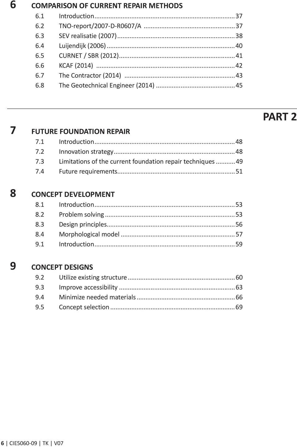
8 1 INTRODUCTION 1.1 Background In the Netherlands there are more than 7 million houses of which roughly are built on wooden piles (CBS, Deltares, 2012). It is estimated that in the upcoming decades about of these wooden pile foundations need repairing (CURNET/SBR, 2012). Wooden pile foundations were used, mainly in the western part of the Netherlands, up to the 1970 s. Problems with this type of foundation are mostly caused by wood decaying fungi, bacterial degradation or insufficient load capacity. In some occasions the wooden pile foundation can be preserved by, for example, bringing the ground water level above the wooden foundation parts again. Often more drastic measurements are needed like underpinning the building with new piles and pouring a new concrete floor slab which transfer the loads from the structural masonry walls to these new piles (see figure 1.1.1). Herewith risks, nuisance and in particular costs can increase severely. Nowadays, the Dutch government and local authorities offers little possibility to either subsidize the repair or to hand out low interest loans for foundation repair. It is also difficult, if not impossible, to get, for instance, provinces, municipalities or water boards (Waterschappen) liable for foundation problems because a plot owner is considered responsible for its own plot and these parties often simply lack the means to act. Hence the costs for foundation repair are most often entirely for the homeowner. Homeowners can either be housing associations that often own entire building blocks but don t have the finances for large scale foundation repair or individual homeowners for whom financing the needed repair is also often challenging. Furthermore with today s economy, property values are declining and increasing an existing mortgage is getting more difficult if not impossible. Moreover, a property doesn t increase much in value after the repair since all the money is put underground. However, if the foundation is in poor condition the property will decrease value, hence, if no action is taken means taking big losses. Making foundation repair possible more often means a need for cheaper and more efficient construction methods which can compete with the conventional methods available. Therefore there is a need to do research on existing construction methods in search of innovation. It is particularly important to get the costs down and the repair less impairing to the homeowners. Figure Construction of new concrete floor slab on piles (Brefu, 2014). 8 CIE TK V07

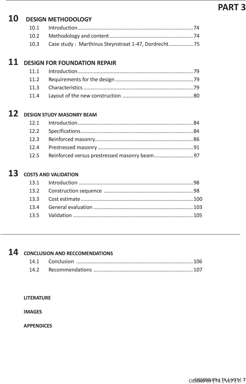
9 Figure Risk of settlement differences (left) and areas where wood decay can occur (right), Western Netherlands (Deltares, 2012). CIE TK V07 9
, Western Netherlands")
10 1.2 Problem definition If no measurements are taken to deal with foundation problems, these buildings will be become uninhabitable. Buildings will undergo unacceptable settlements thus tilting and crack development will get worse over time. As a consequence, a thorough repair of the building envelope or even jacking of the whole building might be needed. This means an increase in costs which eventually will probably become too high to salvage a building. Therefore the execution of foundation repair in time is essential and necessary. The current varies construction methods for foundation repair have an average cost of about euro per house (Luijendijk, 2006). These high costs, the nuisance to expect, execution risks and additional costs are the reason for many homeowners to postpone or even forget about foundation repair. This minimizes the urge for general maintenance of the building which means that entire neighbourhoods will endure pauperization eventually. Changing the way foundation repair is being executed won t happen overnight. It will take some time before new materials and techniques are accepted in the often conservative construction world. To make this possible, funds are needed to invest in research. Not only to come up with new methods but also to validate this method to be safe and that it can compete with already existing methods. Within the existing construction methods it can however be assumed that enough research is done to get the costs down, both by contractors and engineering firms. Hence it is likely to gain the most by searching for new innovative solutions for foundation repair. Part of this thesis will explore some of these options. 1.3 Research question What are the innovative possibilities that offer a cost-effective solution in the construction method of foundation repair? Sub questions: How and with what knowledge current foundations are usually build? What foundation problems have arise over the years and how serious are they? What kinds of foundation repair methods are used? What are the advantages and disadvantages of the current construction methods? What does foundation repair cost? What materials or combination of materials can be used for foundation repair? What are the developments regarding foundation techniques and can they be applied to foundation repair? 1.4 Case study A case study is chosen to find out whether the new construction method to conceive can compete with existing methods. Herewith an existing building or a whole building block is considered which has foundation problems and where it has been shown that foundation repair is needed. Design requirements and boundary conditions will be set. The case study should be a representative example. This can, for instance, be a block of terraced houses with an adjoining street frontage, no room for storage of building materials, different settlement behaviour, and so on. 10 CIE TK V07

11 1.5 Objectives Charting the history of wooden pile foundations and the problems encountered over the years. This section will primarily serve to provide some background information to clarify how the foundation problems arise and how serious the problems really are. This will be done through a literature review. The inventory of existing foundation repair techniques and the risks, costs and nuisance that come a long. The various existing techniques can be found in the literature and will be described thoroughly. The information on risks, costs and nuisance will be obtained mostly from aggrieved homeowners, contractors and engineering companies. Much information can also be found at the KCAF. Finding a cheaper and more efficient construction method for foundation repair and determining the feasibility. Finding a new cost-effective construction method will be the innovative and most challenging part within this thesis. There is also extensive research needed on materials, techniques and methods. The feasibility is tested by the case study mentioned earlier. Draw a conclusion about the ability to innovate within foundation repair by comparison with the existing methods. The findings of the extended research together with the case study should lead to answers concerning the innovative possibilities in foundation repair. 1.6 Project strategy The final thesis will start with an introduction followed by three parts and ends with a conclusion and recommendations. The following is a description of the three separate parts. Part 1 analysis of wooden pile foundations and foundation repair techniques The scope and boundaries within innovative construction methods will be determined in this part. It will give the outline of the report which is necessary in order to achieve a good outcome and will function as a guideline for the second part. The following parts will be analysed: - The historical use of wooden pile foundations and the problems encountered over the years. - The conventional design methods for foundation repair. - The comparison of current repair methods. With the result of this part the first two objectives will be achieved and this section will provide the required input for the second part. Part 2 conceptual design The requirements and boundary conditions determined in the first part will be analyzed here. The problems and possible contradictions found shall be solved through innovation. To innovate, recent developments in materials, engineering and construction methods will be studied. A large part of the information is taken from the literature, but also interviewing fellow students, teachers and especially people in the field may contribute to finding an innovative solution. For an analytical approach to the problem is chosen for TRIZ (Theory of Inventive Problem Solving) (Rantanen and Domb, 2008). The solutions found are then placed in a morphologic overview from which different concepts will arise. In consultation with the graduation committee and with the use of a performance matrix it will be determined which concept to choose for. This part will result in a conceptual design that will be used for elaboration in the third part. CIE TK V07 11

12 Part 3 design validation In this part the design will be developed to enable the comparison with a conventional construction method. Validation of the design must be determined. Most importantly; the design must be feasible and able to compete with existing construction methods. The comparison is done through a case study mentioned earlier. This part along with the other two parts will discuss the conclusions and recommendations. Here, moreover, the last two objectives are achieved. Below is a schematic outline of the thesis. In the literature review foundation repair is analyzed. The research will provide a conceptual design and subsequently a validation of the design should be apparent from the case study. Figure Outline of the thesis (by author) 12 CIE TK V07

13 PART 1 Analysis of wooden pile foundations and foundation repair techniques

14 2 THE DUTCH SOIL 2.1 Introduction The Netherlands is mainly a low and wet river delta to the North Sea. The four main rivers (Rhine, Meuse, Schelde and IJssel) and the influence of the sea have strongly formed the Netherlands and have determined the Dutch soil structure. About half of it is below sea level and would be flooded if there were no dikes, dunes and pumping plants. Land forming has been stopped, but subsidence continues by slow tectonic movements. The subsidence of the land and rising sea water level makes it necessary to raise dikes in order to maintain the country (Verruijt, 2012). 2.2 Geotechnical aspects The soil, in particular, in the Western the Netherlands consists of a thick Holocene layer of clay and peat to a depth of 12 to 17 meter under Amsterdam Ordnance Datum (Normaal Amsterdams Peil, NAP). This layer directly underneath the surface lacks sufficient bearing to for instance build a multi-storey masonry building on. Below the Holocene soft soil layer is, however, a Pleistocene sand layer which provides more than sufficient bearing strength for that. This sand layer is used since the 17 th century in the Netherlands for pile foundations. A famous example of a building on wooden pile foundation is the old City Hall of Amsterdam built between 1648 and 1665 on piles (Gans, 2011) (see figure 2.2.1). 2.3 Hydrology More than 90% of the soils have groundwater within 140 cm of the soil surface during the winter. Therefore, most Dutch soils have hydromorphic properties and require artificial drainage (Hartemink, 2013). The groundwater moves relatively poor threw the soft soil of the Holocene layer. In most cities of the Western Netherlands is the upper aquifer formed by sand embankment that has the water table as its upper boundary. A main cause of foundation damage is often due to groundwater variations. All data on groundwater, used polder levels, dewatering carried out in the area, and so on, throughout the life of the building, are important. A large percentage of the foundation damage in the Netherlands can be led back to unforeseen effects of changing groundwater levels (CURNET, 2007). Geotechnical and hydrological information in combination with technical information of the building can be used to explain the load deformation behaviour and to determine the load bearing reserve or lack of reserve of a structure. Figure City hall amsterdam (Berckheyde, 1673) 14 CIE TK V07


15 3 THE HISTORY OF WOODEN PILE FOUNDATIONS IN THE NETHERLANDS 3.1 Introduction In the last few decades the renovation of old neighbourhoods and restoration of historical buildings happens on a large scale in the Netherlands. When considering whether to restore, renovate or demolish a building or whole building block the state of the foundation can be decisive. This does not mean that the degradation of a building is only determined by the quality of the foundation but it can play an important role. Renovation or restoration starts with assessing the existing foundation. To enable a good assessment it is important to understand how foundations were constructed. This also determines what kind of foundation repair is needed. This chapter is about the foundation techniques used till the 1970s. 3.2 Foundation types The first buildings in the Netherlands were lightweight timber framed houses without any foundation. The lack of foundation caused rather large settlements in the soft soil (peat and clay). Hence buildings needed to be lifted after a while. The bearing structure was just a timber frame put directly on the ground which obviously decays rapidly at the underside. In the 11 th century an improvement came with the use of masonry like blocks (kloostermoppen) which kept the timber frame from the soil and increased the footprint on the soil. The introduction of masonry made it necessary to improve the load bearing capacity of the foundation. The soft soil in the Western Netherlands couldn t carry the relatively heavy masonry walls. Hence a deep slit was dug somewhat wider than the wall would be. Short thin piles (slieten) of alder (elzenhout) were hammered into the ground. Then a grid of more short thin piles was placed on top. On this foundation thick oak planks were placed on which the masonry was put (see figure 3.2.1). In the 14 th till 16 th century an improvement came by using thicker and longer (5-7 m) piles of alder. First again a deep slit was dug below the water table (phreatic surface) and oak beams were placed in the longitudinal direction on both sides with head beams to form a grid. The piles were driven in the spaces between. Since these piles weren t long enough to reach the dense sand layer (12-15 m) they were only supported by skin friction (Janse, 2003) (see figure 3.2.2). Figure Wooden pile foundations with short thin piles (slieten)(curnet/sbr, 2007). CIE TK V07 15


16 Figure Foundation types 13-14th century (CURNET/SBR, 2007) In the Dutch Golden Age, roughly spanning the 17 th century, they drove even longer piles up to the first substratum. Now the piles and its loads were mainly supported by a sand layer at the tip. These piles have been driven to refusal ( op stuit ) and were all cut on the same height well below the water table. Since the bearing capacity of the piles was increased the distance between the piles became larger. A wooden plank floor was placed on the piles whereupon they could start there masonry. Over time this foundation type was of course improved but the principle maintained the same (see figure 3.2.3). Figure Foundation types 16-18th century (CURNET/SBR, 2007) 16 CIE TK V07

17 The wooden pile foundation was used till the 1970s. The most common types in Netherlands were the Conventional, Amsterdam and Rotterdam method. These were all rather similar as can be seen in figure The wooden piles were from pine or spruce depending mainly on the needed length and availability. When foundation repair is needed for buildings dating from 1850 to 1945 these three foundation types are most commonly found (CUR, 2012). Conventional and Amsterdam method With both methods two piles are driven in the width of the foundation perpendicular to the longitudinal direction of the foundation. On top of the piles a head beam named a kesp is put on its side. Then beams (langshout) are placed in the longitudinal direction of the foundation. The beam consists of rib wood (schuifhout) to prevent the wall sliding sideways and wooden floor plates (vloerhout) to support the masonry. The hart distance between the pairs of piles is about 1.0 to 1.5 meters. The use of two piles instead of one was to increase the load bearing capacity of the foundation and stability during construction. Rotterdam method With this method no head beams are used only wooden floor plates with a lath (schuiflat) on top to again prevent the wall sliding sideways. The floor plates are somewhat wider than the pile diameter to deal with small errors when driven the piles. In this method the piles are loaded more centric. This often gives fewer problems than the Conventional or Amsterdam method where the head beams can fail due to eccentric loading or insufficient load-bearing capacity. With all three methods the beams are often broken or punctured by the pile heads or masonry. This is caused by the loads on the beam bearing upon its side, which can bend and crush into the longitudinal fibres. Figure Clockwise form top left, Conventional, Amsterdam and Rotterdam methode (CURNET/SBR, 2007). CIE TK V07 17

18 Figure Piling at the Diemenstraat, Amsterdam, 1897, Breitner ( ) (Gans, 2011). 18 CIE TK V07
")
19 4 FOUNDATION PROBLEMS 4.1 Introduction Insufficient bearing capacity of wooden piles will cause settlement. This can be stabilized by redistribution of the load which is provided by the stiffness of the building. This stiffness can stop any further settlement. However, if the settlement differences are large and ongoing the building will tilt, crack and eventually become uninhabitable or even structurally fail. Insufficient bearing capacity of wooden pile foundations can be caused by (CURNET, 2007): incorrect pile lengths; an uneven bearing stratum; increase in load by e.g. renovations or extensions; broken or splitted piles due to horizontal loading; construction errors; degradation of wood (or masonry); negative friction. The first four of the above reasons require no further explanation. The following chapter will provide information on negative friction and degradation of wood and masonry. Followed by what cracks can tell about the settlement behaviour and how to investigate wooden pile foundations. 4.2 Negative friction Till about the 1930s the term negative friction was unknown in construction practice (Tol, 2006). This negative friction gives an additional load to the foundation piles which can be as high as the load on the pile head itself. The magnitude of this kind of friction depends on the relative displacement of the soil compared to the pile and adhesion of the soil on the pile. The loads can be increased by, for example, embankments or lowering of the water table which consolidates the subsoil. The negative friction will, even when the point bearing capacity is exceeded, always cause significantly less settlement of the pile than the ground level. The problem is settlement differences which damage a building. This is mainly caused by the difference in deformation behaviour between the piles. Some piles act stiffer if placed in a better sand layer. If all piles were showing the same behaviour than negative friction wouldn t cause much damage. Street levels were often raised higher than the building site and courtyard (Hogervorst, 1975). Therefore more sand was needed. This increased load resulted in larger settlement of the street compared to the building site and courtyard. Besides, by raising the street level again and again over the years the settlement also increases. This is partly the reason why the front side of a building experience the relatively largest settlement like in the centre of Amsterdam at the canals. Here, another factor of importance can be that the water level at the canal is kept too low relatively to the ground water level causing local consolidation of the subsoil. Embankments to raise the street level can also cause horizontal movement of the soil. This can result in the horizontal loading of piles which can then break or split (see figure 4.2.1). CIE TK V07 19
: incorrect pile lengths; an uneven bearing stratum; increase in load by e.g. renovations or extensions; broken or splitted piles due to horizontal loading; construction errors; degradation of wood (or masonry); negative friction.")
.")
20 Figure Negative friction (CURNET/SBR, 2007). 4.3 Degradation of wood Wood, together with stone, is the oldest construction material in the world. Wood is a renewable material, while concrete and steel are not. Service life has known to exceed 500 years (Bijen, 2003). The durability of wood depends largely on the environment to which the wood is exposed and its type. The performance of wooden pile foundation can decrease with time mostly due to biological attack. Decay by fungi From experience it is known for quite some time that the ground water table must be kept well above the wooden pile foundation to limit decay by fungi. Fungi is the most serious threat to wooden structures that are not fully submerged in water. They cause decay of wood by disintegrating the lignin and cellulose which are two of the most important components of wood. In nature the fungi is really important since they provide nutrients to the soil by decomposing organic and inorganic materials. Fungi in wooden pile foundations, however, can be disastrous. The sapwood is most vulnerable to decay. Decay fungi needs wood (food source), oxygen (fungi are aerobic organisms), water and appropriate temperatures. The most favourable temperature for decay is between 19 and 31 ⁰C (Bijen, 2003). The temperature at foundation level in the Netherlands will always be a bit lower but the other three components mentioned are abundantly available and decay is facilitated. The wood decaying fungi can be divided in four groups: brown rot, white rot, soft rot and wooddisfiguring fungi. Local conditions like moisture content of the wood and oxygen levels determine 20 CIE TK V07

21 which fungi are the most active. Among wooden pile foundations soft rot fungi is the most liable for the decay of wood. This fungus needs less oxygen to survive than do brown rot and white rot fungi and therefore prosper in wood exposed to soil and water (Bijen, 2003). For wooden pile foundations in the Netherlands mainly pine and spruce were used. They are both equally vulnerable for decay. The degradation stops when the water table is well above the wooden pile foundation again. Figure Rotten pile heads due to decay by fungi (left) and rotten head beam punctured by pile head (top) (CURNET/SBR, 2007) (Vasiljevski, 2012). Bacterial attack Bacteria degrade all wood in almost all environments. Even very low oxygen concentrations can be enough to degrade wood by bacterial attack. The cellulose of the wood is mainly attacked which happens slowly compared to soft rot. Nevertheless problems arise in the Netherlands with slowly deteriorating wooden piles below ground water table. The degradation will be the largest at the pile head and decreases with depth. Local conditions like soil profile, hydrology and contaminations determine the progress of bacterial degradation in wooden piles. For wooden pile foundations in the Netherlands they mainly used pine and spruce. The sapwood of pine is slightly more susceptible for bacterial degradation than the sapwood of spruce. For the heartwood of both species it is the other way around. The sapwood of pine is relatively thick compared to that of spruce. For the shorter and therefore often thinner piles they most often used pine (5-8 m). These thinner foundation piles often have to deal with strong bacterial degradation. Other types of wood used for foundation piles in the Netherlands are larch, fir, oak and alder. CIE TK V07 21
22 4.4 Masonry As with most old buildings in the Netherlands the transfer of the loads from the structure to the foundation is provided by heavy masonry walls. When considering foundation repair it is important to understand the changes to the state of balance and to the pattern of load distribution of the masonry during all phases of the repair. Knowledge of the effects of age on the durability and performance of masonry is essential. Also, calculations and tests must be done to determine the residual strength of the masonry. The outcome is often a rather conservative design value for compression strength of 1,0 to 2,5 N/mm 2 (CURNET, 2012). An extended research can give higher values but the costs for research will obviously also increase. The load bearing capacity can decrease because of (Thorburn, 1993): lack or loss of adhesion (large continuous cracks); loss of material strength; loss of bearing length on the wooden pile foundation; corrosion of metal parts in masonry; distortion caused by foundation movements. The quality and composition of the brick or mortar used can differ per building. Bricks before 1900 were produced locally with clay or slip from a river nearby. Appearance and strength of the brick depends on composition of the clay, type of dry- and baking process and reached temperatures during baking. The size of the bricks also differs per region and it was until 1901, when the Housing Act (Woningwet) was introduced, that rules were set about the minimum exterior wall thickness. Since the Housing Act the common wall thickness was about 200 to 220 mm. During the 20 th century the quality of brickwork became more constant. This, however, doesn t mean that the compression strength of old bricks is constant today. Because of this a rather low value for the residual compression strength is taken between 5 and 15 N/mm 2 (CURNET, 2012). Till about 1900 all buildings were constructed with lime mortar. With this, lime is used as binder and sand as the aggregate. When together mixed with water this becomes mortar. Lime mortar can endure slow deformations rather well without showing cracks. Notice that slow in this sense means that it can deal with deformation caused by, for instance negative friction. Cement mortar was introduced around From then on cement is used as the binder which improved the strength but made the mortar more brittle which decreased the deformation capacity. The amount of lime and cement determines the stress-strain characteristics (see figure 4.4.1). Another possibility is a combination of both, also called bastard mortar(fraaij, 2000). Compressive strength (N/mm2) cement mortar bastard mortar lime mortar Strain (0/00) Figure Stress-strain diagram mortar (Fraaij, 2000). 22 CIE TK V07
23 Masonry damage is often associated with damp conditions in which lime mortar can deteriorate considerable over time. Damp conditions can also result in a sulphate attack on mortar, the source of the sulphates being the bricks themselves. Situations have occurred where the cement mortar had deteriorated in strength to such an extent that the mortar could be removed just by scraping the surface (Thorburn, 1993). The changes in the strength of mortar as well as bricks can cause problems during foundation repair, particularly when the foundation repair involves excavations. When excavating underneath a foundation the masonry should be able to arch safely over the excavations. If the masonry is too weak or too fragmented then repair work should be carried out to strengthen the structure at foundation level. In general, structural strengthening, together with foundation repair, is essential to restrict movements. CIE TK V07 23
24 4.5 Cracks The appearance of cracks can indicate the location and size of the foundation problems. If cracks coincide internally and externally this is a fairly clear indication of foundation damage. Also of great importance is to find out whether the situation is stationary or ongoing. The size and shape of the cracks can be used as damage indicators. Distinction can be made by (Bullivant, 1996): - crack patterns; - the edge of the crack; - wall surfaces (comparing movement of walls and floors). Crack patterns Horizontal cracks at ground level often indicate possible foundation damage in an early stage. Vertical cracks across the facades of buildings can also indicate foundation damage. A significant factor is the positioning of these cracks together with their widths. Vertically cracking occur at the bearings of lintels or between windows. Similar cracking also occurs at the junction between existing buildings and new extensions or with adjacent buildings where no expansion joint is used (Bullivant, 1996). Tapering cracks indicate distortion. The terms hogging and sagging are used to explain the likely effect of tapers in cracks. Sagging cracks tend to be the widest at ground level and with hogging the widest cracks will occur higher up towards roof level (see figure 4.5.1). Crooked walls, sloping floors, cracked lintels, sticking doors and windows and broken sewages are additional indicators of foundation problems (Bullivant, 1996). Edge of the crack When looking to a crack in detail, information can be found on when the crack appeared and which kind of deformation occurred (Bullivant, 1996): A young crack has sharp edges with colour differences at the inside compared to the air exposed outside. These cracks are caused by tension or bending stresses. Comparable young cracks with crumpled edges and loose grit indicates shear stresses. Worn corners and no discoloration can be caused by (seasonal) altering crack profiles throughout the year. If crack widths and deformations stay small and constant no immediate action is needed. Wall surfaces Another solid indicator of foundation damage is the comparisment of the movements of wall surfaces and floors. This, combined with information on cracks can give good insight concerning the settlement behaviour of the foundation (Bullivant, 1996). All of the above should be viewed only as indicators. Additional evidence should be found to confirm foundation damage. Figure Hogging (left) and sagging (right) (Lange, 2011). 24 CIE TK V07
25 4.6 The survey process of wooden pile foundations Most wooden pile foundations were constructed before any regulations were set concerning strength, stiffness, stability let alone serviceability. Foundations before 1950 were designed empirically without a Cone Penetration Test (CPT) or any geotechnical calculations. The piles were driven to refusal and not test loaded. Also the negative friction wasn t taken into account until the 1950s. Consequently wooden pile foundations often don t meet today s Dutch building regulations (Bouwbesluit Bestaande Bouw, VROM, 2005). Yet, it is known from experience that a wooden pile foundation in good condition can have a long residual life. Therefore a Dutch guideline is set in 2011 to investigate wooden pile foundations using slightly different standards compared to the normal Dutch building regulations in order to determine the preservation period. Below is a brief explanation about the methods of investigation. For a detailed overview reference is made to the Onderzoek en beoordeling van houten paalfunderingen onder gebouwen [F 3 O, 2011]. Methods of investigation during foundation research are: The desk study to collect all the relevant information available about the building, the foundation, adjacent building, etc. The visual inspection provides the inventory of aspects that indicate foundation problems by inspecting the inside of the building and the façade. Crack widths are determined visually. Tilt measurements to determine the deformation of the building (settlement differences and rotation) and obliquity of the walls and façade by levelling. Height measurements to relate the original construction level with the current one and to determine the settlement velocity of the building. Maps, archives (N(AP)), NAP and measuring bolts (meetbouten) are used for this purpose. Inspecting the surroundings to obtain information which can be relevant for functioning of the foundation. Such as loads from abutments, excavations nearby, embankments, trees, vibrations, etc. Groundwater table measurements to obtain an indication of the current groundwater level relatively to the wooden pile foundation. The foundation inspection to gather information about the state of the wooden pile foundation. Inspection pits are excavated to classify the soil profile and determine the quality of the masonry (and concrete). These pits are also used for a visual inspection of the wooden pile foundation, and tests and calculations are done to determine the residual bearing strength of the wooden piles. Sometimes piles are test loaded, but this is optional. Laboratory tests to determine what is causing wood decay and to predict the strength loss for the next years. A full survey must be completed to evaluate the quality of the wooden pile foundation, and to estimate the life expectancy for the upcoming decades. The foundation can be classified after examine the bearing capacity of the wooden pile foundation and the sand layer it stands upon. If the foundation is damaged badly the information on the cause(s) and consequences can be used to determine what kind of foundation repair is needed. Rotation Type of damage Name Crack width Name < 1:300 None Very small < 0,5 mm Very small 1:300 1:200 Architectonic Small 0,5 1 mm Small 1:200 1:100 Architectonic Medium 1 3 mm Medium 1:100 1:75 Structural Large > 3 mm Large > 1:75 Structural Very large Table Names related to rotation (left) and crack width (right). Table Names related to rotation (left) and crack width (right) (F30, 2011). CIE TK V07 25
26 5 CONVENTIONAL METHODS FOR FOUNDATION REPAIR 5.1 Introduction There are basically four general categories of foundation repair (Bullivant, 1996). Remedial: Remedial foundation repair to restore stability, strength and stiffness of a building. This most often is the case in the Netherlands due to the already mentioned insufficient bearing capacity or deteriorated foundation. Conversion: Foundation repair may be needed when converting a building which increases the loading onto the foundation such as a vertical extension or structural alterations. Protective: Protection against external adjacent work such as tunnelling, excavations, vibrations, etc. Mining: Mining subsidence as a wave during mining and later as gravitational settlement can affect a building. Foundation repair in time is necessary and can involve the use of a jacking system to provide adjustment for ongoing future settlements. Within this thesis only remedial repair is considered. However the other categories mentioned above often require quite similar repair methods. It is often necessary to strengthen and temporarily support the structure of a building before doing any foundation repair, particularly if the structural displacements take the form of significant tilt or lateral movements. It must also be noted that not every construction method is suitable for every type of foundation or soil condition. Information about the pile types used for foundation repair is given below. The conventional construction methods for repair will be discussed next. This will give an overview of the possible foundation repair methods available. Part of the information is derived from the CURNET / SBR Handboek Funderingsherstel and CURNET / SBR Funderingen Deel A, A4000 uitvoeringstechnische aspecten. 26 CIE TK V07
27 5.2 Pile types A pile foundation is used when the soil directly underneath the building lacks sufficient bearing capacity or is too soft causing excessive settlement. There are several pile types and piling techniques available. Which pile type and piling technique to choose from depends on: Space availability, including restricted access and limited headroom. Construction method for foundation repair. Dimensions of the piling equipment. Desired bearing capacity. State of the abutments and its foundations. State of the building itself. Planning permission. Tubular steel piles are used almost exclusively in the Netherlands. These piles are sectionalized and fitted with a welded collar or at times a screw joint. Installing the steel piles in sections and using small machinery makes execution in a limited space possible. All of them are soil displacing cast in situ systems (see figure 5.2.1). Information on the available piling techiques is given on the next few pages. Figure Classification of bearing pile types (Thorburn, 1993). CIE TK V07 27
28 Driven piles This method is used for installing steel tubular piles by means of bottom, top or high frequency driving. Information about the three is given below. Bottom driven tubular steel piles are most commonly used for foundation repair in the Netherlands. This piling technique can be used for both small and large diameter piles. The pile is driven internally by a heavy weight winched up to drive down onto a dry concrete plug (prop) at the foot of the pile. Driving the pile at the bottom moves the vibration source away from ground level which limits the pile driving vibrations. Therefore this method is considered almost vibration free (trillingsarm) (see figure 5.2.2). Driving steel piles from the top is done with a modified jackhammer only for small diameter piles. A disadvantage, compared to bottom hammering, is that the vibration source stays above ground and the pile driving vibrations will increase when reaching the bearing sand layer. Moreover the penetration of the pile decreases due to greater pile-soil interface causing the pile to move down more difficult. In addition the gravity centre of the pile and hammer stays at the top which increases the likelihood of pile buckling during driving (Choe, 2002). For high frequency driving a compressed air driven ram is placed on top of the pile. This method is used only for piles with a small diameter in foundation repair. With this technique there are still some uncertainties in determining the drivability and end bearing strength in advance. Therefore the piles sometimes need to be redriven with an impact hammer for acceptance as a bearing pile (Rausche, 2002). With all of these three methods grout mortar is sometimes injected during driving. This way it is intended to lower the driving resistance and also to increase the bearing capacity of the soil. When the piles are installed at the calculated pile tip level they are filled with concrete. A general term for these piles would be driven steel cased in situ concrete piles. Figure Bottom driven pile (Waalpaal, 2014). 28 CIE TK V07
29 Screw piles Tubular steel piles are screwed into the ground up to the required depth. Sometimes grout mortar is used during installation of the piles which is meant to lower the driving resistance and also to increase the bearing capacity of the soil. This technique is vibration-free which is an advantage in foundation repair (see figure 5.2.3). With this method it is difficult to check whether the pile has reached the bearing sand layer. Therefore a thorough soil investigation is needed to be certain the bearing resistance will be sufficient. The screw blade together with the tubular steel pile will remain in the ground. The pile will encase the concrete poured afterwards if not already filled with grout during installation. Figure Screw injection pile (Goorbergh, 2014). Jack-down piles The jack-down method is a silent and vibration-free method where all the piles can be tested when installed. The piles are installed by hydraulically pushing short sections into the ground. The jack must be secured adequately to ensure a sufficient working load provided by the dead load of the structure (see figure 5.2.4). This system can be used in confined spaces. With jack-down piling the CPT information is verified by measuring the jack pressure. In this way alterations can be done if there are large deviations. If the pile doesn t reach the required depth, pile driving is occasionally needed. Other pile types used for foundation repair are segmental precast concrete piles (betonsegmentpalen), segmental precast concrete piles encased by steel (buissegmentpalen) and open-ended steel piles (pulspalen). If foundation repair can be executed externally than in some cases driven or screwed soil displacing cast in situ systems can be used. However it is often complicated to get the heavy piling equipment on site. CIE TK V07 29
30 Figure Jack-down system anchored to the floor (Waalpaal, 2014). 5.3 Strengthening by adding piles If the wooden pile foundation is still intact the load bearing capacity can be increased by adding piles. The easiest way is to drive piles at both sides of the bearing masonry wall as close as possible. On top of these new piles a concrete head beam is poured and then the joint between the concrete head beam and wood is closed with wedges. The ground water level must be recovered well above the wooden foundation afterwards (SBR171, 1985). When repairing old foundations often the foundation masonry also needs repairing. The joints can be degraded which affects the cohesion and therefore strength. Repair can be done by e.g. chemical injections. Replacing parts of the old wooden pile foundation or adding new piles and connecting them with the existing foundation was done frequently in the Netherlands. Especially during city renewal when renovating entire building blocks. Nowadays strengthening of the existing foundation is less common. 30 CIE TK V07
31 5.4 Lowering wooden pile heads If the groundwater table is constantly kept too low, the pile heads and other woodwork will decay by fungi. Subsequently the foundation is slowly losing its bearing capacity and will eventually fail. To restore the bearing capacity the rotten parts must be replaced. This is done by cutting the wooden piles well below the lowest groundwater level known (paalkopverlaging) and removing all the other deteriorated parts. It is also important to be certain that the quality of the masonry is still sufficient. Then the removed pile sections are replaced by steel compression struts (spindels). These struts are prestressed and eventually encased by reinforced concrete. Sometimes shoring is used to provide temporary support to the structure while foundation repair is executed (see figure 5.4.1). With this repair method an entrance to the foundation is needed from the front or side of the building. A passage is made in the façade below ground level from which point the foundation is excavated and the soil disposed. The ground water table will be lowered temporarily by an open drainage. By repairing the old foundation it will get back its original load bearing capacity. This method can only be used if: Foundation piles are almost exclusively from spruce (better resistance against bacterial degradation); Only the top part of the piles are deteriorated; The other foundation parts are still sufficient (survey and test loading); The loads are not increased too much (by e.g. vertical extension or structural alterations). With this method no additional bearing capacity is added. When the bearing capacity is insufficient the foundation can be strengthened by adding piles as mentioned earlier. Via weight calculations and the existing foundation plan, calculations are done to estimate the pile loads. Historical data about wooden pile foundations can provide more information if needed. To get planning permission geotechnical calculations are also needed to prove there is enough load bearing capacity. It must be noted that adequate data is often difficult to obtain. DIN-16 DIN-16 DIN-16 DIN-16 DIN x x x 20 existing section existing new section existing new side section view new section side view side view section section existing existing new section new section side view side view section section 15 oak x x oak oak section 2-16 oak 2-16 oak section 2-16 section section section top view top view top view top view top view detail detail detail detail detail Figure Temporary support for pile head lowering (CURNET, 2007). CIE TK V07 31
32 5.5 Floor slab piling Floor slab pilling, better known in the Netherlands as the table method (tafelmethode), can be used when the whole foundation needs replacement. With this method a whole new reinforced concrete floor slab is poured which is connected to the bearing walls with needle beams (inkassingen). New piles transfer the loads directly through the slab onto a bearing stratum. The old foundation remains there but loses its function. It is nearly impossible for the old foundation to maintain its structural function since the new piles have a different settlement behaviour which can cause large settlement differences and stresses in the construction. There are basically four construction variants: After demolition of the ground floor, a new reinforced concrete floor slab is poured. Then recesses in the floor are used to jack down the piles. After the (partial) demolition of the ground floor, piles are placed and then the reinforced concrete floor slab is poured. Without demolition of the ground floor, apply a new concrete floor in the crawlspace after excavation. Then recesses in the floor are used to jack down the piles. Without demolition of the ground floor, the crawlspace is excavated, piles are placed and then the reinforced concrete floor slab is poured. It depends on the structural condition, expertise of the contractor and the client requirements which method to choose. With two of the four construction variants listed above, the concrete floor is already there before piling. Herewith the floor is used to anchor the hydraulic jacks. The anchors incorporate the weight of the building to generate sufficient resistance. This must be equal to the working load of the pile plus its factor on safety. Interesting fact is that the stiffer the floor is, the more counterbalance can be taken from the structure above. With jack-down piling the CPT information is verified by measuring the jack pressure. In this way alterations can be done if there are large deviations. After removing the jack, the head of each pile is set into the floor slab by grouting up or concreting the pile head. The recess has a tapered shape to transfer the loads efficiently to the piles. The grid pattern of the piles will of course depend on the loadings, and needle beams are provided at centres up to 1.2 meters. Figure Floor slab piling (VROM, VNG, 2009). 32 CIE TK V07
33 The last two listed construction variants are especially interesting when a basement is constructed with the repair. When having a basement floor below the highest ground water level extra measures should be taken to keep the water out. The minimum required headroom to work in is only 1.5 m in the Netherlands. This little working space makes the work more complicated and therefore more costly. Clearly, this low height is also inefficient later on. 5.6 Jack-down piles from or directly underneath a wall Jack-down piling is a silent and vibration-free method which uses the dead load of the building to produce sufficient resistance to equal the working load of the pile times a safety factor. This method can be used for foundation repair but also to stabilize, straighten or upgrade existing foundations. The maximum distance between the piles is limited to about 2.0 m mainly because of arch action in masonry. To jack-down piles from the ground floor, basement or crawlspace, large wall recesses are made. From this recess (inkassing) a hole is drilled up to the underside of the foundation between the existing wooden piles. Thereafter a steel casing can be inserted, secured with grout, to include the weight of the foundation. The piles (d mm) are then jacked in sections to the calculated depth. It is important that the old structure is competent in itself to withstand the jacking. After the required preload is set the space between the pile and masonry or steel casing gets filled with grout. When all the piles are placed and preloaded, the old foundation loses its function because the load is taken by these new piles. Finally the jack is removed and the recess is closed with brickwork and if needed finished with plaster (see figure ). Figure Jack-down piles from a wall (VROM, VNG, 2009). CIE TK V07 33
34 For piling directly underneath the foundation, a pit is excavated below the foundation to provide a working space for the hydraulic jacks. The water table must temporarily be lowered. The piles are jacked in sections directly underneath the heart of the existing foundation. A reinforced concrete foundation beam is needed to transfer the loads from the masonry bearing walls onto the piles. The existing masonry must of course be in good condition to transfer these loads. temporary recess ground floor jack-down pile filled with grout steel casing secured with grout crawl space drill-hole wooden pile foundation pile tip var Figure Jack-down piles from a wall at ground level (VDM, 2014). 34 CIE TK V07
35 5.7 Cantilever pile and beam or ring beam The cantilever pile and beam can be used to (locally) strengthen an existing concrete foundation beam. A strip of about 1m is needed at the in- or outside of the building as a working space. The tubular steel piles are then placed close to the existing foundation to limit bending moments. Then short steel needle beams (consoles) are placed on top of the pile heads. After preloading, the needle beam and part of the pile, are encased with concrete for corrosion protection. A cantilever ring beam is quite similar to the cantilever pile and beam, but in this case the piles are connected with a reinforced concrete ring beams external to the wall being supported. The two are connected with needle beams. There is also a need for a working space of about 1m wide at the full length at the in- or outside of the building. This method can be used if there is no existing concrete foundation beam which is often the case with wooden pile foundations. Figure Cantilever ring beam from the outside (VROM, VNG, 2009) (top), detail drawing cantilever pile (CURNET 2007) (left). CIE TK V07 35

36 5.8 Pile foundation with prestressed concrete beams With this construction method the piling is done outside at the connection between the longitudinal side walls and the walls at the front and rear of the building. A free workspace of about 2 m wide is needed for piling. After piling, the wall is cleared beneath the ground floor at both sides which provides a workspace to construct the prestressed concrete beam. Hereby, the ground floor will stay intact. Needle beams in wall recesses transfer the loads from the bearing masonry wall via the prestressed concrete beam to the new piles. Sometimes the beams are connected by cross beams. To apply a prestressing force to the concrete the beam is post-tensioned. Special ducts are installed in the mould before the concrete is cast. Next, tendons are installed and, after casting and hardening of the concrete, they are stressed. The end faces of the concrete beam are used as supports for the jacks. Anchorages are used to stress the tendons. The ducts are injected with grout which bonds the tendon to the duct. Now the forces are transferred from the tendons to the concrete and the tendon is protected against corrosion (Walraven, 2012). This method is restricted only for walls with a length no longer then 10-12m. Existing cables and pipelines can give problems during execution. first floor pressure box hydraulic jack wooden piles Figure Prestressed concrete beam applied (CURNET, 2007). 36 CIE TK V07
37 6 COMPARISON OF CURRENT REPAIR METHODS 6.1 Introduction This chapter provides an overview of the costs, nuisance and risks attached to each of the, in the previous chapter mentioned, foundation repair methods. Most information is derived from reports (which are briefly summarized and commented) and by interviewing practitioners. The interviews can be found in the appendix. 6.2 TNO-report/2007-D-R0607/A Scope This report compares the construction methods for foundation repair in relation to costs, risks and nuisance. It was commissioned by the ministry of VROM to compose a document on foundation repair of buildings with wooden pile foundation. This report is mainly written for homeowners who have to deal with foundation problems. As a result, the information given is rather basic. Research First, some background information about wooden pile foundation is given with a brief description on the available foundation repair methods, followed by the comparison of different repair methods in relation to costs, risks and nuisance. The construction methods are categorized (A1, A2,...D2) and an indication of the construction costs is given. The table below is derived from the report, translated in to English. Method Variant Costs [euro/m2] Total costs x [euro] Pile Head Lowering A1 from ground level ca. 40 A2 from crawl space / basement ca. 40 Floor Slap Piling B1 from ground level ca. 70 B2 from crawl space / basement ca. 60 Ring Beams C1 prestressed concrete beams ca. 50 C2 cantilever beams ca. 60 Jack-down piles D1 from ground level / inside ca. 50 D2 from crawl space or outside ca. 50 Table Indication of construction costs (TNO, 2007). These figures are only indicative since other factors influencing the costs are not taken into account. For example, an important factor not included is the refurbishment costs when the ground floor must be removed. Following the outline of the costs are the risks and nuisance stated per method. Not only are the risks during execution mentioned, but also the general risk of settlement differences in a building block due to partial foundation repair. Forms of nuisance for the residents can be time duration, noise and vibration. A table is given below to summarize the findings. CIE TK V07 37
38 Method Variant risks costs foundation repair costs refurbishment time duration ( 1-3 months ) noise nuisance vibration nuisance influence on garden/pavement property out of use filth and damage inside Pile head lowering A1 ++ o A Floor Slap Piling B B Ring Beams C1 + o o C Jack-down piles D1 o D2 o + o o favourable for residents with respect to o - unfavourable for residents with respect to o Table Comparison of different foundation repair methods (TNO, 2007). Notes This report merely provides basic information on comparison of the available repair methods. Most information is obtained by speaking with contractors who obviously have their own interests. No information is given about how the information is to be interpreted. Furthermore, the construction costs might be outdated (2007) and additional costs are mentioned but without any indication given. 6.3 SEV realisatie (2007) Scope SEV was commissioned by the Dutch ministry of VROM to evaluate the approach to foundation problems of six municipalities which are Dordrecht, Gouda, Haarlem, Schiedam, Waddinxveen and Zaanstad. Topics covered roughly are: how the money is spent, which policy choices are made, which foundation repair methods are used and what are the costs per dwelling. Also information is given about financing programs and the process approach per municipality. Research Chapter five and six of the report can provide some information on foundation repair costs for this thesis. First some general information about foundation repair methods is given. Followed by a description of which repair methods are used in each municipality and what the average costs are per dwelling. The two tables below give the outcome of both. Method Dordrecht Gouda Haarlem Schiedam Waddinxveen Zaanstad Pile head lowering, from inside x x x Floor slap piling x x x x x x Jack-down piles, from inside x x Prestressed concrete beams x x x x x Infiltration system, preventive x Table Used foundation repair methods (SEV, 2007). 38 CIE TK V07
39 In Dordrecht an infiltration system is used, as a preventive measure, where the wooden pile foundation is still in good condition. Gouda has used the floor slap piling alternately which can only be done if there are no interior bearing walls. Municipality Average costs per dwelling [euro] Dordrecht Gouda Haarlem Schiedam for repair, for renewal ( ), m (1,9 dwelling per building) Waddinxveen ( ) Zaanstad ( ), (2006) Table Average foundation repair costs per dwelling (SEV, 2007). The prices differ because of e.g. a different surface area of the building, weight of the building, needed pile lengths, used foundation repair method and procurement market. The possibility to (partly) subsidize the repair or getting a low interest loan varies per municipality. Notes by author The report covers foundation repair on a large scale. There is therefore no information given on how much each repair method costs. The average costs to repair the foundation of a dwelling might be outdated (2007) and can be considered rather low. This is probably because the figures are provided by the municipalities and not by the homeowners themselves. Additional costs like refurbishment costs are most likely not included. Risks and nuisance is not covered here. CIE TK V07 39
40 6.4 Luijendijk (2006) Scope This report examines the technical and economic impact of foundation problems in relation to groundwater. It gives an insight in what consequences an alternating groundwater level has on the preservation and development of old city centres. Research The first part of this research is about (ground-) water in the Netherlands followed by the relation between ground water, urban areas and real estate. The second part covers the technical and economical consequences of alternating groundwater levels. In chapter six it is held that the magnitude of the repair costs is between and euro. This includes the costs for structural repair (cascoherstel). It is estimated by Luijendijk that the average cost of foundation repair will be about euro. A case study is done to estimate the repair costs. A, for Dutch standard, average sized dwelling (A = 9x6 m 2, V = 400 m 3 ) is used as a model. The calculation of the total repair costs is done by using the average costs of the most common foundation repair methods available. The author specifies the costs in detail based on statistics of and knowledge within Grontmij 1. The results are given in the table below. 1 European company in the Consulting & Engineering industry. Foundation repair Adding foundation piles Ring beam Dwelling 400 m 3 [euro] (17 piles) Average [euro] Placing foundation piles (17 piles) Ring beam Replace wooden pile heads with concrete Ring beam (33 pile heads) Repair of settlements till 250 mm Repair of cracks Repair of leaking pipes 325 Repair of Supports Repair of window frames 230 Repair of window 95 Repair of plantation 250 Repair of pavement Total Table Potential costs for total repair (Luijendijk, 2006). Notes In this research some of the additional costs are included but no distinction is made between the different foundation repair methods. It is not clear whether it is assumed that all the work can be done from underneath the ground floor or if the ground floor is removed. Some parts are oversimplified and it is never emphasized that the costs can be much higher. 40 CIE TK V07
41 6.5 CURNET / SBR (2012) Scope The CURNET / SBR foundation repair manual has already been used and referred to in this literature review. The manual not only discusses the technical issues of foundation repair but also the related legal, insurance, organizational and financial aspects. Research Chapter 5 deals with the different repair methods for pile foundations. In addition to information about specific properties and preconditions are the advantages and disadvantages of each method given. The latter is used to compare the different foundation repair methods of which a summary is given below. Floor slab piling* + Jack-down piles can be applied vibration less and the piling equipment is small which limits the risk of damage. + The hydraulic jack is assembled on location whereby it can be used in confined spaces or areas with restricted access. + The concrete floor can provide extra stability during execution which reduces the chance of structural damage. + When all the piles are in place the whole building can be levelled by jacking. Jack-down piles are difficult or even impossible to use if the soil penetration resistance is high. If the concrete floor is poured before piling it will give an additional load onto the old foundation which can lead to further damage and settlement. This will however generally not give any problems when executing full foundation repair. * Only floor slab piling with jack-down piles is considered here. While driven or screw piles are also used in practice. Jack-down piles from or directly underneath a wall + This method can be used in small spaces by using small pilling equipment. Residents most of the time don t have to leave their home. + Floors and internal walls don t need to be removed. + Refurbishment costs are relatively low. + Construction time is relatively short. + The method can be used for partial foundation repair (locally adding more bearing capacity). + The method is flexible. Jack-down piles from a wall is only possible if the masonry is strong enough and if the building can provide enough reaction force by its own weight. The pile diameter is limited which also off course limits the bearing capacity of the pile. Pile Head Lowering + The costs can be relatively low. + The building remains intact so that the residents don t temporarily have to move. The decay of wood can continue by a future decline of the water table. CIE TK V07 41
42 Cantilever pile and beam or ring beam + The existing structure is utilized. + The ground floor can be (partly) preserved. There will be some nuisance for the residents during execution. Pile foundation with prestressed concrete beams + The dwelling remains intact so that the residents don t have to move. + There are no additional costs like replacing the floor, kitchen and restroom. + The new foundation directly takes the loads after tensioning. + This system can be combined with other systems. Not all dwellings are suitable for this method which mainly depends on its size and shape. This method is usually more expensive than floor slab piling but the additional costs are low thus this doesn t say much about the final costs. The crawl hatch often needs to be moved because of the new foundation beam. Dealing with cables and pipelines can give additional costs. Soil remediation, if needed, can be expensive. Notes The advantages and disadvantages of each repair method are given rather arbitrarily in this manual and how thorough they are described differs per method. This makes it difficult to compare the different construction methods. The manual provides with some information about the pro s and con s of each method separately. There are no figures given on costs merely that, for instance, the one method is relatively cheaper than the other. Risks and construction time are also poorly covered in this manual and there is little information given about the noise and vibration nuisance. 6.6 KCAF (2014) The interview with Dick de Jong, director of the Dutch Knowledge Centre Approach Foundation Problems (KCAF), in which especially information about the societal aspects concerning foundation repair was given, is briefly summarized below. Jong indicated that foundation problems in the Western Netherland are manifest but problems also exist in other Dutch provinces such as Friesland, Groningen and Maastricht. Outside of the Netherlands wooden pile foundations are used, among others, in China, United Kingdom, Germany and Sweden. Nowadays the KCAF is mainly concerned with the possibilities of financing foundation repair. This, especially causes problems in areas where the mortgage exceeds the actual value of the property and/ or the income of the homeowner is simply too low. To deal with this KCAF advocates for a national fund, he explained. Jong stated that providing information to the people about the available repair methods is important since they re mostly ignorant and hence don t understand why repair is that expensive. In this, he argued, municipalities have the responsibility to guide their citizens and hand out low interest loans. 42 CIE TK V07
43 Furthermore, Jong stated that floor slab piling is used most often nowadays due to the fact that for a Permit for Physical Aspects (omgevingsvergunning) the reference period is 50 years which is most easily met by replacing the whole foundation and floor. Jong argued that the costs for repair differ per situation but on average is about euro per square meter. Supervision during construction and a carefully drafted plan of action will help to handle costs, he stated. He concluded that the amount of people involved in foundation repair still is rather small while the problem is growing. Jong stated that this will change in the near future, under the condition that the financing problem will be solved. 6.7 The Contractor (2014) Four contractors were interviewed for this thesis in order to get more background information and, if possible, information on recent developments within foundation renewal. All four of them represent well known reputable Dutch foundation repair companies. Their names, together with the companies they represent, are listed below. Mr. Company Technique(s) de Waal Walinco - Several piling techniques, mostly driven and screw-injection piles. Hillen Revac - Jack-down piling, often small projects. Prins P. van t Wout - All foundation repair techniques, except jack-down piling. van der Wel Van Dijk - Jack-down piling, often large projects. The interviews consist of three main topics which are repair techniques, costs and innovation. Most interesting findings are given below and summaries of all interviews can be found, in Dutch, in the appendix. It must be said that the contractors all have an economic interest and thus will gain by promoting the repair techniques they offer. Floor slab piling Waal stated that roughly 95% of foundation repair of housing in the Netherlands nowadays consists of floor slab piling. The applicability of this method depends on things like local conditions, shape and size of the house, wall thicknesses and needed pile lengths. Prins stated that it is about 80% of the total. According to Waal, placing a concrete floor and jack-down piles afterwards is done less often these days. Waal believes, although vibration free, the method to be labour intensive and therefore costly. He stated that screw injection piles are used instead. Wel, however, claimed that jack-down piles are still used frequently, especially in the area of Rotterdam. Prins mentioned that bottom driven steel piles are still most frequently used, simply because it is the cheapest method, he explained. In urban areas Prins observes an increasing use of screw piles due to unwanted vibration, noise nuisance and risk of damage. Sometimes this is used in combination with grout-injection. The needed piling equipment is about the same size as for pile driving. Prins emphasized that floor slab piling is a combination of repair and having a new concrete floor instead of the old wooden floor joists. This leaves the possibility for floor heating and tiles can be applied. Jack-down piling from the wall Hillen explained that with jack-down piling from a wall the new piles are under centric load, which is not the case with most other foundation repair methods. He also stated that the work is always executed with as little nuisance as possible and argued that this method is primarily for small renovation projects like e.g. partial foundation repair of a house. Wel, however, told that jack-down piling is perfectly suitable for larger projects when demolition and repair work should be limited. They both agree when renovating whole building blocks, floor slab piling is most often a cheaper and more efficient option. CIE TK V07 43
44 Wel acknowledged that the pile diameter is always limited by the wall thickness and added that the dead load of a building is usually sufficient to jack-down piles. However, the heart distance of the piles is limited by openings in the wall or lack of masonry stiffness. Prins explained that this repair method is not used by P. Van t Wout since it is kind of a specialization within foundation repair. Moreover, both him and Waal have their doubts about the small applicable pile diameter because they believe there is a risk of buckling or falling out of plumb. Waal stated, furthermore, that this method is most often the more expensive one, because more piles are needed. Prestressed concrete beams When the foundation is accessible from the outside the prestressed concrete beam method can be used, said Prins. This method is preferred by him only if the ground floor must be preserved. However, applicability of this method is limited by size of the house, length of the walls, depth of the old foundation and whether the possibility exists to place the piles outside of the building. Pile head lowering It is noted that pile head lowering is rarely used nowadays, mainly because municipalities often don t find it a sustainable solution which Prins, however, stated that this varies. If only the upper part of the foundation is rotten and there for bacterial degradation or negative friction plays no part, pile head lowering can be a suitable option. Prins explained that the advantage of this method is the fact that the rest of the house remains intact. A downside is, especially when there is much groundwork to be done, that the costs can add up vastly. Poor working conditions and relatively large risks are also reasons why this method is only used in few exceptional cases, he said. Cantilever pile and beam or ring beam Waal explained that for light weight structures such as in parts of North Holland a ring beam can be used. But when having thick bearing walls of 20 cm or more and a building height of about 5 to 10 m, floor slab piling is mostly a better option. He believes this is because concrete is relatively cheap and not a lot of formwork is needed. Prins similarly asserted that floor slab piling is a better solution in most cases. Prins stated that with a detached house a concrete ring beam can be used outside. Downside to this is that no interior walls or columns are supported by this ring beam which, if present, can cause settlement differences. Costs All four interviewed contractors state that the costs for foundation repair diverge. According to Waal the costs are determined, in particular, by accessibility and the time it takes to get the piles into the ground. Furthermore he stated that it is often more cost-effective to remove the ground floor instead of executing the work from below. Also, profit can be made by using experienced engineers, who can optimize the design, and skilled people to write the specification. Waal and Prins both mentioned that conducting foundation repair simultaneously can be more cost-effective. According to Wel, it is always difficult to estimate the condition of a property in advance. With jack-down piling from a wall, the lack of knowledge on quality of the masonry and location of the old foundation piles can give problems during execution. Hillen mentioned that with jack-down piling labour is about 75% of the costs. Although the repair is often relatively more expensive, refurbishment costs will be much lower. Wel told to believe that labour will be about 60% of the total price and when, for instance, 30 piles are needed the costs will roughly be about euro. It was emphasized by him that this includes finishing. According to Prins, screw-injection piles are about 1,5 to 2 times more expensive than bottom driven piles which is mainly because of the lower production rate and higher material costs. He asserted that, after excavation and demolishing work is done, the piles especially scew-injection piles will be the most expensive, followed by reinforcement and concrete. Laying reinforcement is labor-intensive since 44 CIE TK V07
45 reinforcement mesh cannot be used because of accessibility and layout of a building. Prins estimated that when only constructing a concrete floor with piling, for a house of e.g. 6 by 12 meters, the costs will be about euro of which about 40% will be labor, 60% other. It is emphasized by Prins that excavation work can be really expensive, especially when soil remediation is needed. 6.8 The Geotechnical Engineer (2014) Two geotechnical engineers were interviewed in order to get a better idea about what kind of role they play within foundation repair and what kind of situations they come across. Their names are Arnold van Gelder, geotechnical advisor at Fugro, and Arjen van Maanen, project manager at Wareco. Most interesting findings are given below and summaries of both interviews can be found, in Dutch, in the appendix. Foundation research Maanen noted that Wareco gets approached for foundation research by private homeowners as well as housing associations. In some occasions, these housing associations carry out foundation research just as a preventive measurement for maintenance plans or when they want to sell some of their properties. Research for the latter is needed because in several municipalities they can only sell knowing that the foundation will suffice for the next twenty-five years. Maanen stated that this is a good way to ensure the quality of old buildings. Wareco conducts research in accordance with the F 3 0 guideline, affirmed Maanen. At Fugro, Gelder mentioned, the guideline is used but in a pragmatic manner by looking at the requirements set by a district or municipality. When foundation repair is necessary, no indication is given about which repair method should be used. The report will only tell whether anything should be done and within what time frame. Maanen explained that if the foundation still suffices Warenco in some occasions not only gives an enforcement period, but also the advice to e.g. raise the water table. Furthermore, Maanen told that the cause of foundation damage differs per city. He argued, for example, that in the city of Zaandam they have used relatively thin wooden piles ( mm) and bacterial degradation can be severe. On the other hand, in Dordrecht there are many problems with dry period, often in relation to sewage problems. Gelder argued that, since all wooden pile foundations are finite, partial foundation repair most often isn t an option because over time a new problem will start elsewhere. In addition, problems can arise due to the difference in deformation behavior between the old and new parts of the foundation. Maanen similarly asserted that partial foundation repair is mostly not a good solution. Costs Maanen indicated that the cost for foundation research ranges from to euro. According to van Gelder, the costs are on average about euros. More specific, he explained, that the desk study and tilt measurements cost around euro, excavations can easily cost euro, foundation inspection around euro and laboratory tests and reporting around euro. The approval of a foundation usually requires more research than the disapproval, indicated Maanen. He added that if the indications of foundation damage are really clear, research is not necessary. Gelder argued, however, that it is always worthy to conduct tilt measurements to get an indication of the rotations. Herewith, the aspects that indicate foundation problems can be related to these measurements. Maanen and Gelder both think that there is not much possibility to save costs within foundation research. Gelder suggested that cost per individual can drop when homeowners execute research simultaneously. CIE TK V07 45
46 Conclusion By analysing wooden pile foundations and foundation repair techniques the first two objectives given in paragraph 1.5 are achieved. Moreover, this part will provide guidance for the second part; concept development. End of Part 1 46 CIE TK V07
47 PART 2 Concept development
48 7 FUTURE FOUNDATION REPAIR 7.1 Introduction This part of the thesis will be a search for a potential innovative foundation repair method. Different concept designs will be developed through innovation one of which will be elaborated on in Part 3 design validation. In this chapter the innovation strategy used will be explained first. Applications and limitations of current foundation repair techniques are briefly summarized in the next paragraph followed by a description of future requirements. 7.2 Innovation strategy An innovation strategy is needed to efficiently search for a potential future repair method. The schema below illustrates of which components Part 2 concept development exists and in what sequence they are treated. The boundary conditions and requirements will first be determined with the use of the literature review of which a concise summary is given in paragraph 7.3. These future requirements are analyzed to derive three design principles. The problems and contradictions found shall be solved by innovation. The design principles will be used, together with a morphological model, for concept designs of which one will be selected for further elaboration in part 3. Figure Content of part 2 (by author). 48 CIE TK V07
49 7.3 Limitations of the current foundation repair techniques Current foundation repair techniques all have limitations in terms of reducing costs, risks and nuisance. From previous chapters it can be concluded that over the years these repair methods are optimized but still there is a need for a more cost-effective foundation repair method. The limitations of current foundation repair techniques can be found below, which basically is a concise summary of chapters 5 and 6. Applications Costs Pile head lowering Nuisance Risks Applications Costs Floor slab piling Nuisance Risks Applications Costs Jack down piles Nuisance This method can only be used when the wooden foundation piles are from spruce, only the top part is deteriorated by fungi, the other foundation parts are still sufficient and no additional bearing capacity is needed (5.4). The costs can be relatively low (6.2, 6.5, 6.8). However, if there is much groundwork to be done the costs can add up quickly (6.7). An advantage of this method is that the house remains intact and nuisance is limited when executing the work from the outside or underneath the ground floor (6.2, 6.5, 6,7). Poor working conditions, relatively large risks and uncertainty about the sustainability are reasons for this method only to be used occasionally nowadays (6.2, 6.6, 6,7). Floor slab piling is the most used method, between 80-95% for foundation repair in the Netherlands (6.7), where the entire foundation is replaced by a concrete floor slab on piles. This method can almost always be used but is rather drastic since usually the ground floor needs to be removed in order to execute the work (5.5, 6.2). The costs are relatively high, especially when including the refurbishment costs (6.2). Sometimes a basement can be constructed with the repair, leaving the ground floor intact, but is believed to be even more expensive (6.7). Nuisance is large, in particular, when the floor is removed (6.2). Screw-injection piles and jack-down piles are used to limit noise and vibration nuisance (6.5, 6.7). The risk of damage is relatively small which is mainly because a whole new foundation is constructed while the old foundation is left alone (5.5, 6.2, 6.5, 6.7). It is held that this method can be used not only for total foundation repair but also to stabilize, straighten or upgrade existing foundations. There are, however, different opinions on this kind of partial repair (5.6, 6.7, 6.8). The heart distance between the piles is limited mainly because of arch action in the masonry. And the pile diameter is limited by the wall thickness and competence of the old structure (5.6, 6.5, 6.7, 6.8). In two reports it is claimed that the costs for this method are relatively low (6.2, 6.5). Contractors, however, stated that when e.g. renovating a building block, floor slab piling is often a cheaper and more efficient option (6.7). It is emphasized by several persons that the refurbishment costs will be much lower (6.5, 6.7). Labour is about 60-75% of the total costs (6.7). Advantage of this method is that it is vibration free and the piling equipment is relatively small. The floor doesn t need to be removed and work can be done per pile (5.6, 6.5). Therefore residents don t have to leave or e.g. a shop doesn t need to close (6.5, 6.7). CIE TK V07 49
50 Risks Ring beam Applications Costs Nuisance Risks The lack of knowledge on quality of the masonry and location of the old foundation piles can give problems during execution. There are some doubts about the applicable pile diameters (6.7, 6.8). The cantilever ring beam can be used, in particular, for light structures, to strengthen an existing foundation, external to the wall being supported, at the in- or outside of the house (5.7). It is, however, argued by contractors that when executing the work inside, floor slab piling is mostly a better option since concrete is relatively cheap, not much formwork is needed and there is instantly a new floor. When using a ring beam at the outside no interior walls or columns are supported (6.7). The costs can be relatively low if the work can be executed from the outside which is obviously only possible if the property is detached. When doing the work from the inside most of the floor often needs to be removed which will increase the refurbishment costs considerably (6.2, 6.5, 6.7). Pile driving will give noise and vibration nuisance. When the work has to be done from the inside, and the floor needs to be partly removed, this will cause even more inconvenience to residents. The risk of damage is relatively small which is mainly because a whole new foundation is constructed while the old foundation is left alone (5.7, 6.2). Applications Costs Prestressed concrete beams Nuisance When the foundation is accessible from the outside this method can most often be used (6.7). Applicability of this method is, however, limited by size and shape of the house, length of the walls (10-12 m), depth of the old foundation and the possibility of placing the piles outside of the building (5.8, 6.7). Existing cables and pipelines can give problems during execution (5.8, 6.7). The cost is about average (6.2). Plus there are no additional costs since the work is done outside and underneath the house (6.5). Costs can however add up if there is much groundwork to be done (6.5, 6.7). The ground floor remains intact so that residents don t have to move. There will be vibration and noise nuisance (5.8, 6.2). Risks Risks are comparable with the floor slab pilling and ring beam method (6.2). In addition, for all methods it can be said that conducting foundation repair simultaneously is often more cost-effective and prevents the risk of any further settlement differences within a building unit (6.7, 6.8). This, however, can be at times difficult since some homeowners, regularly, don t have the finance or simply don t want to participate (6.6). It is stated by contractors as well as the KCAF that the costs for foundation repair diverge (6.6, 6.7). This makes it difficult, if not impossible, to for instance determine a square meter price per method. The requirement for getting a building permit in the Netherlands is that a new foundation will last at least 50 years which is partly a reason why floor slab piling is used the most (6.6). There are also parties that, if the foundation is in reasonable condition, look at e.g. soil improvement or other preventive measures. Research on this is still rather new (6.6). Partial foundation repair is believed not to be a durable solution since wooden pile foundations are finite and over time a new problem will arise elsewhere. Plus it can give problems due to the difference in deformation behavior between the old and new parts of the foundation (6.8). 50 CIE TK V07
51 7.4 Future requirements Instead of focusing on the limitations of current foundation repair techniques, attention is shift to a potential new repair method, from now on called solution. The boundary conditions and requirements, determined by the problem definition in paragraph 1.2 and the literature review in part 1, will be analyzed below. Incidentally, the terms boundary conditions and requirements are in practice fairly used interchangeably. Here, the concept boundary conditions is used for externally imposed criteria and the concept requirements for the criteria that the solution must satisfy. Together they will be called future requirements. Boundary conditions Finding a more cost-effective construction method for foundation repair is, as explained in the first chapter, the main objective within this thesis and therefore is the most important boundary condition for a solution. Aspects such as risks, nuisance and time-duration, which can give problems and contradictions, are considered as well. The cost is believed to be determined, in particular, by accessibility and how long it takes to get the piles into the ground (6.6). Finding an e.g. enhanced piling technique for the latter will be beyond the scope of this thesis. Accessibility, however, can probably be improved by, for instance, searching for a technique where most of the work can e.g. be done outside or needed excavation and demolition work is limited. Aspects such as reducing man-hours or changing the type or amount of applied materials can also help get the costs down. Time-duration is often strongly linked to costs since the longer the repair takes the more it will cost. In addition, if the repair takes longer nuisance will be larger, especially when the property cannot be used during the repair. Noise and vibration nuisance must also be taken into account when searching for a solution. For vibrations, there are often rules drawn up by the local municipality to limit the risk of damaging the structure of the house itself or adjoining houses. The overall risk of damage must be minimized. Not only during execution of the repair but also, later on, as the house is occupied. The biggest risk over time would probably be the unwanted settlement differences which obviously have to be excluded. In the Netherlands most houses with wooden pile foundation are terraced or multi-family houses in urban areas (CBS, SYSWOV, 2012). These 2-5 stories high buildings often have a direct street frontage. It is commonly difficult to get to the back with e.g. heavy piling equipment. The boundary between two properties is, most often, formed by a masonry load-bearing party wall with a thickness of at least 20 cm and there parallel to a, mostly 10 cm thick, load-bearing partition wall. Application of a solution must preferably not be limited by the size, shape or weight of the building. But all of the above should be kept in mind when in search of a solution. Foundation repair in itself can be regarded as a sustainable solution since the building will stand for roughly a hundred or more years while the required resources are relatively small, especially when compared to demolition and rebuild. The most frequently cited definition of sustainability is used here which defines, ``Sustainable development is to ensure that we meet the needs of the present without compromising the ability of future generations to meet their own needs. (WCED, 1987). In other words, sustainability is reached when satisfying present needs without endangering the needs of future generations. Sustainable design will be an additional boundary condition when searching for a solution. CIE TK V07 51
52 When considering sustainability, questions that arise might be: - How does the solution minimize energy consumption? - How does the solution minimize resource consumption? - Is the solution designed to withstand long-term impacts of climate change? - Does the solution incorporates any renewable or low-carbon energy technologies? NB: Costs for foundation-, geotechnical-, and environmental research and planning permission are not considered. Topics like low interest loans, subsidizing programs as well as legal right of neighbours are not covered. Requirements For foundation repair in Netherlands there is the requirement to comply with building regulations. These building regulations can be found in the Buildings Decree 2012 (Bouwbesluit 2012), in Dutch, and the building rules drawn up by a municipality. Moreover, in most cases, a Permit for Physical Aspects (omgevingsvergunning) is needed. The Building Decree contains the technical regulations that represent the minimum requirements for all structures in the Netherlands. These requirements relate to safety, health, usability, energy efficiency and the environment (Rijksoverheid, 2014). 52 CIE TK V07
53 8 CONCEPT DEVELOPMENT 8.1 Introduction The future requirements determined in the previous chapter will be analyzed here. The problems and contradictions found shall be solved by innovation. For an analytical approach to solve problems is chosen for TRIZ (Theory of Inventive Problem Solving) which provides a range of strategies and tools for finding inventive solutions (Rantanen and Domb, 2008). A short description of the TRIZ theory is given in the next paragraph followed by design principles which are partly derived with the use of this theory. To conclude, a morphologic overview is given from which different concepts will arise. This overview together with the design principles will be used in the next chapter for concept designs. 8.2 Problem solving Common features of a good solution is that it resolves contradictions, uses preferably, idle, easily available resources and increases the ideal final result of the system (Rantanen and Domb, 2008). A model is given below. Figure Features of solutions (by author). Contradiction A contradiction is a conflict in the system. In this case the system consists of a building unit with a damaged foundation, which is the object, and foundation repair, which is the tool acting on the object. The contradiction is that the tool is needed to preserve the object, but the price of the tool is too high. This problem can be formulated on more than one level but this thesis will concentrate on how to change foundation repair techniques (see figure 8.2.2). CIE TK V07 53
54 Figure Problem formulated on more than one level (by author). The object gives restraints to the change of the tool. This object can, however, be changed, by e.g. modification, in favour of the tool. The homeowner doesn t need the product provided by the tool but only needs its features, which is stop settlement, tilting and cracking of the house. Moreover, a thorough foundation repair which provides these features involves high costs. So, as with most products, the higher the quality the more it will cost. The trade-off or conflict between the features quality and price needs to be removed by a new, improved system. Foundation repair has, in addition to high costs, many problems and tradeoffs: time-duration, noise nuisance, vibration nuisance, risks, and others. These are, however, not equally important. One problem is key, which when solved leads to the solution of others (Rantanen and Domb, 2008). The inherent contradiction wanting that one thing that has two opposite properties can be formulated as: the homeowner needs foundation repair, and needs no foundation repair. This may sound like an irresolvable contradiction yet it can, according to TRIZ, help to find a solution. Examples of tradeoffs that arise when changing the operations of the system and inherent contradictions behind them are listed below. Problem Trade-off Inherent contradiction Piles Excavation work Demolition work Time-duration... Piles transfer the loads to the bearing sand layer (+) but are expensive (-). Excavation improves access (+) but increases costs (-). Demolition improves access (+) but increases costs (-). Time-duration should be short to limit costs and nuisance (+) but long enough to prevent risks (-). Many-few piles Much-little excavation work Much-little demolition work Short-long time-duration Table Tradeoff and related inherent contradictions (by author). 54 CIE TK V07
55 Resources Resource analysis can help find ways to resolve contradictions. Resources are energy, materials, objects and information that are already in or nearby the problem. Sometimes they can be used directly or just need some modification. Resources depend on the way the system is described but could for instance be: skills of the contractors, literature, existing structure, soil, space, piling machinery and so on. System level Tool Object Environment Macro-level system Micro-level system Resources Contractors, clients, engineers, machinery, materials, connections, current methods. Wooden pile foundation, walls, masonry, floors, crawl space. Soil, air, space, ground water, gravity. Building unit, building block and city. Masonry, brick, mortar, wood, bacteria, fungi, voids, sand, water, concrete, steel, pores. Table Resources listed by system levels (by author). Ideal final result The ideal final result will be obtained by using resources to remove the contradiction. The result provides the more wanted and less unwanted effects at a lower cost, and usually with less complexity. CIE TK V07 55
56 8.3 Design principles Three design principles are determined to achieve the future requirements. Here, the main future requirement cut down repair costs is used, together with the contradictions found in the previous paragraph, to determine the design principles. During the concept development the focus will be on one of these principles per time leading to different concept designs. Exploring the potential of the existing structure in its original state or when modified can reduce costs. Herewith, the quality of the existing structure diverge which must be kept in mind when in search of a solution. Possibilities to incorporate the existing structures are: - Designing a solution that utilizes the existing wooden pile foundation; - Designing a solution that utilizes the existing masonry walls; - Designing a solution that utilizes the existing floor as part of the repair method. With existing buildings in urban areas access is restricted by its structure, adjacent structures, streets, cables, pipelines, gardens and so on. A solution would preferable use the space available without much or, even better, any alterations to the existing situation. This can for instance be done by either: - Designing a solution where all work is done outside the house without excavation; - Designing a solution for inside the house that doesn t require any demolition or excavation. - Designing a solution using low weight machinery and materials which are compact and manoeuvrable so little space and restricted access is enough to do the job. Building material cost money not only buying them but also to transport them to the site and install. Therefore it can be said that costs can be reduced by minimizing the needed materials. Reducing the amount of needed materials can for instance be done by; - Designing a solution that reduces the amount of needed piles; - Designing a solution that only applies materials where needed; - Designing a solution where the loads are transferred more efficient to the piles. As a conclusion of the above, three design principles are determined: 1) Utilize existing structures 2) Improve accessibility 3) Minimize needed materials These design principles will be used together with the morphological model, given in the next paragraph, for a concept design. 56 CIE TK V07
57 8.4 Morphological model All foundation repair techniques share common characteristics. These characteristics all have different options which are presented here in a morphological model (figure 8.4.2). A basis is formed by selecting one (or more) option(s) per characteristic for a more detailed repair technique. It must be noted that with this model numerous combinations can be made. Yet most of them will not give a solution which fulfils the future requirements given in Paragraph 7.3 or are simply not rational or even possible in the real world. To avoid an abundance of solutions the future requirements together with the design principles and ideal final result must be considered when selecting a combination of characteristics. A brief explanation of the morphological model is given below followed by the model itself. This model together with the design principles will be used in the next chapter for concept designs. Structural Support Load transfer Connection Material Old structure Preparation Groundwork Demolition The left part of the morphological model shows the structural characteristics. Here, a masonry load bearing wall of a building is schematized as a mass (see figure 8.4.1). Different options to support the mass are given. There are different options to transfer the loads from the wall to the piles. Here, also a combination of options is possible. Options to connect the wall to the element that transfer the loads are given. Not all connection types are possible in combination with chosen support and load transfer characteristics. This part characterizes the materials used for foundation repair. A combination of materials can be chosen to optimize a concept design. The old exisiting structure is a resource which is already there. Different options to utilize the old structure are given. The right part of the model shows the most important charecteristics when dealing with an existing structure. Different options for groundwork are given. The option to keep or remove the existing floor can be selected here. Figure Schematization of masonry load bearing wall (by author). CIE TK V07 57
58 58 CIE TK V07 Figure Morphological model (by author).
59 9 CONCEPT DESIGNS 9.1 Introduction This chapter will provide three concept designs developed with the use of the design principles and morphological model presented in the previous chapter. These three are rather extreme cases stated by using the design principles for the selection of characteristics which ensure the concepts are not alike. However, in a later stage alterations of course can be done to optimize the design. It must be noted that per design principle multiple designs can be devised. Yet in this chapter only the most promising are presented of which one will be selected for elaboration in part 3. The three design principles, determined in the previous chapter, are: 1) Utilize existing structure 2) Improve accessibility 3) Minimize needed materials The structure per concept design will be as follows: Characteristics per design principle Explanation of which options are selected per characteristic together with the associated illustrations from the morphological model. Description of the concept design A short description and illustration of the design is given. The construction principle and use of materials is explained. Evaluation A concise evaluation is given where the ad- and disadvantages are discussed per concept design. These evaluations will be used for the concept selection. CIE TK V07 59
60 9.2 Utilize existing structure The existing structure is a resource that is already there. Including this resource into a foundation repair method could help reduce costs. Pile head lowering is a current existing method which utilizes the existing wooden piles but, as already discussed, has its limitations and risks. Other possibilities to (partial) use e.g. the existing masonry wall, floor joists or damaged wooden pile foundation are considered in this paragraph. The chosen characteristics from the morphological model are given below together with a brief explanation. Characteristics A3_B3_C1_D3_E1_E4_ F2_G4_H1 Explanation First, it must be decided which part(s) of the existing structure is used for foundation repair. Excavation work is always needed to get to the old foundation which most often is expensive and can be risky. Floor joists could be used for some kind of formwork but are structurally not strong enough to e.g. transfer the loads of the wall to the new piles. The wall itself, however, does already have to transfer the loads to the foundation and probably could have some more potential by increasing its strength and stiffness. Herewith, the idea is to consider the wall as a structural beam which therefore probably should be modified e.g. by using Fibre Reinforced Polymers (FRP) and/or injection techniques. The supports are placed outside the house so no demolition is necessary and excavation work is limited. A recess will provide the connection. Description In order to use the existing masonry wall as a structural beam some modifications are needed. Figure illustrates the required components. Post-tensioned cables are placed just under the ground floor at both sides of the masonry wall to apply a lateral compression force which supports, in particular, the bending forces above. These cables can e.g. be made from steel, if protected against corrosion, or Fibre Reinforced Polymers (FRP). To reinforce the wall itself and increase the out-of-plane load resistance, injection techniques can be used in combination with a FRP mesh or FRP cables (see figure 9.2.2). 60 CIE TK V07
61 The front and rear of the house, obviously, has openings (doors, windows, cables, pipelines) which, probably makes it difficult or even impossible to apply this technique, hence a cantilever beam is used here. This cantilever beam can possibly be combined with the pressure block needed for the post-tensioned cables. Piles can have a somewhat larger diameter since they are only applied outside thus larger machinery can be used which minimizes the amount of needed piles. Herewith, driven or screw-injection piles can be applied. Figure Concept design with structural modified masonry beam and post-tensioned cables (by author). Figure Example of a FRP mesh that structural reinforces a wall (Fibrenet, 2014). CIE TK V07 61
62 Masonry is strong in compression and relatively weak in tension. Hence an eccentric compressive force P m is applied in order to keep the beam free of any tensile stresses at the bottom side. Herewith compression stresses must be kept below a limit value. An illustration of the construction principle is given below in figure Where, the length of the internal lever arm (z), uniform distributed load (q), length (l) and prestressing force (P m ) will determine the compressive force in the arch. Figure Construction principle (by author) Evaluation An evaluation is given below by stating the advantages and disadvantages of this concept design which will be used in the concept selection paragraph at the end of this chapter. Advantages: + Lower costs compared to existing methods. + The existing structure is used. + No demolition work is needed hence no refurbishment costs. + Residents can stay and will experience relatively little nuisance. + Is suitable to apply for a whole building unit. + Groundwork is limited and only outside. + Larger piles can be applied since all the piling is done outside. Disadvantages: Openings in structural partition wall can limit the applicability of this method. The condition of the masonry will differ each time. Upgrading the existing masonry might be expensive. Weight and shape of the building might limit the applicability. 62 CIE TK V07
63 9.3 Improve accessibility Accessibility is used as a starting point for this concept design. Herewith, it is considered most important that the existing structure and its surroundings are harmed as little as possible. The chosen characteristics are listed in the table below together with a brief explanation on the design choices made. Characteristics A2_B1_C1_D1_E3_F1_ G1_H1 Explanation The options for no excavation and keep floor are selected first. This will limit the further possibilities considerably. It is assumed, in general, that crawl space height is limited which rules out the possibility for piling inside, next to the wall, without excavation. As a result the choice is made for a centric support from the wall, where multiple elements are needed since the wall thickness limits the applicable pile diameter. It must be noted that besides piles also e.g. injection techniques, micro-piles and angle piles are considered but applicability of these methods is limited (pile length, state of old foundation, bearing capacity,..) and are therefore not treated here. The loads will be transferred from the wall directly to the piles. Here, it might be interesting to look at improvement of arch action to increase the heart distance between the piles. Recesses in the wall are needed to get the piles in. Jack-down piling is chosen since the machinery is small and hence can be used in confined spaces without causing damage. From the above, it is clear that these design choices made are rather similar to the characteristics of the already existing jack-down piling from a wall method. This method, however, is rather new and it, therefore, might be interesting to look at opportunities for improvement. Figure Cable stayed bridge, Pont de Normandie, France, 1994 (M. Ketchum, 1999). CIE TK V07 63
64 Description As discussed in previous chapters the heart distance between piles, with jack-down piling from a wall, is in particular limited by arch action in masonry and lack of sufficient reaction force from the existing structure. In order to get more reaction force from the existing structure and at the same time tackle the problems with arch action, the principle of a cable stayed bridge is used (see figure 9.2.1). With this bridge type the loads are transferred through tension cables at both sides of a pylon which are converted into compression forces vertically into the pylon and horizontally along the bridge deck. This principle is used here by making a recess in the wall, from which slots are made in the wall from one or both sides to span cables (see figure 9.2.2). These cables are connected to the wall and are subsequently jacked to a pre-determined force and anchored. Next, the segments are hydraulically jacked down to a bearing sand layer. Grouting techniques can perhaps be used to increase the load bearing capacity of the piles. It would also be an advantage if longer segments can be used since this will reduce labour time thus costs. Figure Illustration of the span cable jack down concept design (by author). Figure Detail of the cables slotted into the walls, frame and piles (by author). 64 CIE TK V07
65 Evaluation An evaluation is given below by stating the advantages and disadvantages of this concept design which will be used in the concept selection paragraph at the end of this chapter. Advantages: + Lower cost compared to existing methods + Small piling equipment + Existing floor is maintained + No excavation work needed + Centric support of the wall Disadvantages: Applicable pile diameter is limited. Still need to apply piles between openings. Difficult to determine possible reaction force from the structure. Tension stresses underneath the span cables can cause cracking or worse. CIE TK V07 65
66 9.4 Minimize needed materials Building materials are obviously needed to perform foundation repair. It would, however, be interesting to search for a method where the amount of needed materials is kept to a minimum. The selected characteristics are given below along with a concise explanation. Characteristics A2_B4_C3_D3_E1_E5_ F1_G1_H2 Explanation For this concept design it is chosen that overall renovation is needed thus the floor can be removed and all work is done at the inside. This scenario is very common in practice where most often floor slab piling is applied. Supports are chosen eccentric, for two walls, with multiple elements. This way, very little or even no excavation work is needed and, in addition, this concept design is really different from the other two. Recesses are made to connect the existing structure with the new foundation. The loads are transferred with floor beams to the piles. These floor beams are placed in the lateral direction and are made from reinforced concrete. The formwork for the beams will be provided by Expanded Polystyrene (EPS). The old existing structure isn t used here since a whole new foundation is created. Consequently this concept design can probably be used even if the existing structure is in a really rough state. It must be noted that compared to the other two concept designs more materials are needed. However compared to the, by far most used and comparable, floor slab piling method there is a gain by applying less material. Description For this concept design the idea is to use polystyrene blocks as a formwork to construct concrete floor beams with a concrete topping to instantly create a new floor. The principle is inspired by the already existing beam block composite floor which is a common type of precast floor in the Netherlands (see figure 9.4.1) (CT4281, 2005). One major difference is that with this concept design the beams are cast in-situ instead of precast. Thus the formwork is not only used for the concrete topping but also for the floor beams. An illustration of the concept design is given in figure and a short description of a possible work order is given below. The first thing to do is to remove the existing floor first and prepare the site. Then, piles are driven or screwed into the ground to the required depth and recesses are made in the load bearing 66 CIE TK V07
67 masonry walls. Next, the EPS blocks are placed in between the new piles. Prefabricated reinforcement cages are lowered between the EPS blocks for the floor beams. Additional reinforcement can be added in-situ if needed. A anticrack reinforcement mesh is placed on top of the reinforcement cages and EPS blocks, after which the concrete is poured. Finally a (self levelling) poured screed is used as a top layer on which other finishing materials can be applied. The main advantage of this method would be that less rebar and concrete is needed compared to the current floor slab piling method while still creating a new floor. Hence, this concept design can potentially be a rather good alternative to floor slab piling. Figure Beam block composite floor (Bouwwereld, 2014). Figure Illustration of the concept design (by author). CIE TK V07 67
68 A detailed drawing of the vertical section of the floor is given in figure This drawing shows the EPS blocks between the new piles and the reinforced concrete floor beams in between on top of the new piles. Figure Detail drawing of composite floor (by author). Evaluation An evaluation is given below by stating the advantages and disadvantages of this concept design which will be used in the concept selection paragraph at the end of this chapter. Advantages: + Lower costs compared to existing methods. + Alternating foundation repair is possible. + New floor slab is created, floor heating and tiles can be applied. + Not limited by shape, size and weight. + Reduced floor weight. + Little risk of damage. + Less material is needed compared to the existing floor slab method. Disadvantages: Refurbishment costs can be high. Floor needs to be removed. Nuisance is relatively large. Heart distance between the beams is mainly limited by the loads and compressive strength of the masonry, strengthening of the masonry might be needed. Load transfer from the front and rear facade needs to be incorporated into the design. 68 CIE TK V07
69 9.5 Concept selection All three designs have been evaluated in previous paragraphs according to the future requirements determined in chapter 7. In this paragraph one of the three concepts is selected by looking at the performance of each concept design separately. The one with the overall best performance is selected and will be elaborated further in Part 3 of this thesis. Comparison is done with the use of a performance matrix. It must be noted that the performance of each concept design is presumed upon basic civil engineering knowledge. In addition, extended research on each of the designs could possibly influence the outcome of the concept selection. The chosen names for the three concept design together with their related design principles are: Masonry beam - Utilize existing structure (9.2) Cable stayed support - Improve accessibility (9.3) Composite floor - Minimize needed materials (9.4) Performance matrix A matrix is used to determine which concept design gives the overall best performance (see table 9.5.1). To make a distinction in valuation of the different boundary condition the three at the top of the matrix the most important ones within this thesis can get a score from -4 to +4 and the bottom four from -2 to +2. The total score, at the bottom of the table, indicates which concept design gives the overall best performance and will be selected for part 3. An explanation of how the points are awarded is given next. Masonry beam Cable stayed support Composite floor a. Foundation repair costs b. Refurbishment costs c. Risks d. Applicability e. Nuisance f. Time duration g. Sustainability Total score Table Performance matrix (by author) CIE TK V07 69
70 a. Foundation repair costs Masonry beam (+4) With this design the costs can potentially be much lower compared to the available foundation repair methods. The main reason being that most work is done outside and relatively less building material is probably needed to perform the repair. Although, reinforcing the existing masonry and prestressing the whole wall might be more expensive than anticipated. Further research is needed to understand if this design is feasible. Doing most of the work outside and using the old structure as part of the foundation repair results in a maximum score of +4. Cable stayed support (+1) Less piles thus fewer recesses are needed compared to the current jackdown piling method. This will lower the cost since piling is by far the most expensive. However, the tendons themselves and tensioning of the tendons might be costly and current techniques are still needed between openings. This, in combination with its complexity, results in a score of +1. Composite floor (+2) Less rebar and concrete is needed while still performing foundation repair and creating a whole new floor at the same time. EPS is cheap and easy to handle and prefab rebar cages can be used for the structural beams. Load transfer from the front and rear facade might give some problems hence a score of +2. b. Refurbishment costs Masonry beam (+2) Some plastering might be needed after reinforcing the walls but this would be far less expensive than e.g. replacing the whole floor, partition walls, kitchen and so on. Outside the house cost for redirecting cables and pipelines probably can add up especially when permits are required by local authorities. But altogether the cost for refurbishment will probably be relatively low, which results in a score of +2. Cable stayed support (+3) The design principle for this design was to improve accessibility with as little as possible demolition or groundwork. As a consequence the refurbishment will be low since only the slots and recesses need to be repaired and finished with plaster. Because of the latter not all four points are given, therefore a score of +3 is given. Composite floor (-3) When the floor has to be removed anyway this design probably can compete with current methods. However, when comparison is made with the other two methods and floor removal is not desired refurbishment costs will be relatively high since the floor has to come out, resulting in a score of -3. c. Risks Masonry beam (+0) It is hard to determine what the structural or financial risks could be based on a concept design. Further research and experience is needed to really point out the possible risks for all designs. For now, it can be stated that, for this concept, using the existing load bearing masonry wall as a structural beam could potentially be a risk since it is difficult to determine its quality. However, further research is needed, therefore a score of +0. Cable stayed support (-3) With this method there is probably a structural risk when tensioning the tendons because the masonry underneath the tendons could possibly experience tensile stress and consequently will crack. In addition, there are already doubts about the applicable pile diameter. These uncertainties together, result in a score of -3. Composite floor (+4) A whole new foundation is constructed while the old foundation is left alone. Therefore this design gets a maximum score of CIE TK V07
71 d. Applicability Masonry beam (+0) This design can probably only be used if the existing walls are straight, have sufficient thickness and quality and there are no large openings in it. Most party walls have these characteristics but partition walls often do not. The latter, though the loads are smaller, can limit the applicability of this design, resulting in a score of +0. Cable stayed support (+1) The quality of the masonry must be competent to resist the tensioning of the cables. When the weight of the building is relatively large the heart distance between the piles will be small since the applicable pile diameter is limited to the wall thickness which, consequently, makes it unnecessary to apply span cables. This design is not restricted to the size or shapes of a building therefore is still given a score of +1. Composite floor (+2) This concept design is probably not limited by size, shape or weight of the building. However, the heart distance between the structural beams is most likely constrained by quality of the masonry. Compared to the other two designs a maximum score of +2 is considered reasonable. e. Nuisance Masonry beam (+2) With this design most work is done outside which possibly will limit the overall nuisance. Less piling is needed since large pile diameters can be applied which will result in a reduction of noise and vibration nuisance. This is even more so if, for instance, screw piles are used. Reinforcing the wall and plastering is done at the inside of the house which will give some nuisance to the residents. Because most of the work can be done outside, a maximum score of +2 is assigned. Cable stayed support (+2) All work is done inside the house but repair can be done one pile at a time hence residents can stay. Relatively small vibration free machinery is used for piling. Making recesses and slots in the load bearing masonry wall will give noise and dust nuisance. Altogether, this results in a score of +2. Composite floor (-2) Nuisance is large especially to residents since the ground floor cannot be used during construction. Due to this relatively large nuisance the score will be -2. f. Time duration Masonry beam (+1) When it is assumed that the crawl space is accessible to direct the tendons and cables and pipelines won t give any major problems at the outside, construction time can possibly be short. Time duration will probably also be shorter because no demolition, limited groundwork and little piling, rebar and concrete is needed to conduct the repair. Reinforcing the masonry wall might take some time but the work can be done separately, therefore a score of +1 is given. Cable stayed support (-1) It is already known that the comparable jack-down piling from a wall method is rather labour intensive. With this design less piling is needed but installing the tendons and applying a prestressing force might be time consuming, resulting in a score of -1. Composite floor (+0) Time duration can be short by using prefabricated rebar cages and EPS blocks. However, removal of the floor, possible groundwork and refurbishment after the repair will still cost time, therefore a score of +0 CIE TK V07 71
72 g. Sustainability Masonry beam (+1) Not much resources are needed for this design. It however doesn t incorporate e.g. any renewable or low-carbon energy technologies nor does it minimize the energy consumption for heating of the house since no insulation is applied, thus a score of +1 is given. Cable stayed support (+1) This design is comparable with the post-tensioned wall design in terms of sustainability. Therefore the same score of +1 is assigned. Composite floor (+0) Far more resources are needed compared to the other two designs. But because the new floor is insulated by the EPS blocks energy consumption for heating will probably be lower, hence a score of +0. Conclusion From the performance matrix it appears that the masonry beam design, with a total score of +10, will be used in part 3 for further elaboration. In part 3 it must be determined if this concept is feasible and can compete with current foundation repair techniques. Figure Illustration of selected design (by author). End of Part 2 72 CIE TK V07
73 PART 3 Design validation
74 10 DESIGN METHODOLOGY 10.1 Introduction This part of the thesis will be about the verification and validation of the concept design selected at the end of Part 2. Where, verification confirms that the design properly reflects the future requirements specified in paragraph 7.3. And validation ensures that the design, as provided, fulfils its intended use. This chapter will outline the design methodology used for this part. An overview of this methodology together with the related content is given in the paragraph below. Next, a case study will be presented which will be used throughout Part 3, to give an insight regarding the feasibility and cost-effectiveness of the design Methodology and content Realistic design requirements are set for the case study in order to get a proper design. Moreover, the case study itself must be a representative example of a building unit that needs foundation repair. Different design alternatives are considered and evaluated before choosing the most optimal one. A small design study is done in chapter 12, parallel to the case study, to get more understanding of the possibility to apply reinforcement, whether or not prestressed. Realistic design values for the loads and dimensions are derived from the case study to still provide some coherence but this chapter might be skipped if one is mostly interested in the case study itself. The case study is used in chapter 13 costs and validation for the verification and validation of the design in which the main goal is to determine if the new design can economically compete with current repair methods. In order to achieve this, a comparison is made with the conventional floor slab piling method. This comparison will not tell whether the new masonry beam design will outperform conventional repair methods but is used to reach consensus on the potential of the new design. An outline of Part 3 is given in the figure below. Figure Outline of part 3 (by author). 74 CIE TK V07
75 10.3 Case study : Marthinus Steynstraat 1-47, Dordrecht A block of terraced flats, built in the 1900s, which has experienced severe foundation problems, is selected as a reference model. This building block is considered a representative example, in the Netherlands, because of its size, layout and location (CBS, SYSWOV, 2012). A recovery plan, including a technical solution and cost estimate, will be developed in the upcoming chapters. Background information and drawings are presented below. Background The Marthinus Steynstraat is situated in the Reeland district in Dordrecht (see figure ). This district is considered to be a risk area in relation to foundation problems (Dordrecht, 2013). Figure Location in Dordrecht on the map (top) and street view (bottom) (Google, 2014). The building block is a multiple three-storey structure with masonry bearing party walls, wooden floor joists and pitched roofs. Because the structural party wall is a dividing partition between two adjoining buildings the block must be considered a building unit that, therefore, requires simultaneous foundation repair. These masonry bearing walls are built on a wooden pile foundation according to the Rotterdamse Methode (see paragraph 3.2). Lay out The lay-out of the reference model is presented in the figures below. The dimensions of this model will be used in the next chapter to determine the dead and variable loads which subsequently will be used for the calculations in the design study. CIE TK V07 75
76 As shown below the old drawings are somewhat difficult to read. Therefore a ground floor plan, derived from these drawings, is presented on the next page. The dimensions and layout may slightly deviate from the actual ones but this bears no consequences. Furthermore, only a representative part of the building unit is selected because it is assumed that the needed approach for the other houses will be comparable. Figure presents a ground plan where the two houses at the left are 6,5 meters wide and the one at the right is 5,5 meters wide. All three are 10 meters deep with a small extension at the back. Besides the already mentioned load bearing party walls at both sides there is also a structural partition wall of about 110 mm thick between the passage and living room. Each terraced flat has an apartment at the ground floor with a garden at the back and a second apartment, with a private entrance, at the second floor together with a loft. The entire building unit has an adjoining street frontage hence parking spaces are needed for a construction shed, restroom and storage of building materials. Figure Front and rear facade (top) and plan first and second floor (bottom) (TM, 2011). Figure Selected part of the Marthinus Steynstraat (by author). 76 CIE TK V07
77 Figure Ground floor plan Marthinus Steynstraat (by author). Definition of the problem The following matters should be considered before choosing a construction method for foundation repair: An adequate investigation of the ground and ground water tables. An examination of the condition of the existing structure. Knowledge of the original plans and structural alterations. Problems due to poor workmanship. The possible effect of foundation repair work on adjacent structures. The need to repair brickwork before doing any foundation repair. The decision as to the cause of foundation damage. The influence of the building its surroundings. Any restrictions on noise and the effects of vibration. Any restrictions on building outside the building plot on e.g. municipal land. Space availability, including restricted access and headroom. Legal rights of adjacent owners regarding the withdrawal of support. Within this case study it is, however, assumed that, according to an examination of wooden pile foundations (see paragraph 4.6), the quality of the old foundation is insufficient and complete foundation repair is needed. Moreover, for simplification of the problem, the assumption is made that the condition of the existing structure is in reasonable order and the other matters listed above will not give any problems. CIE TK V07 77
78 Design of current foundation repair Foundation repair through floor slab piling has already been applied in 2011 (Bresser, 2012). Because the repair has been carried out in sequential steps the floors of some houses are (partly) saved but most subflooring and wooden floor joists had to be removed in order to execute the work. At the sections where the floor could be saved a cantilever beam is applied at the front and rear facade to bear the structural loads of these facades. An overall benefit of this design is that no excavation is needed. As already mentioned in paragraph 7.3, floor slab piling is by far the most used method for foundation repair and, therefore, can be considered as a representative example of current repair techniques thus can be used for comparison in the cost estimate in chapter 13. A plan of the repair design is given in the figure below. In this, the light grey areas indicate where floor slab piling is applied and the somewhat darker grey areas indicate application of a cantilever beam. The locations of the needed recesses and tubular steel piles are also given. Figure Part of the foundation repair plan Marthinus Steynstraat 1-47 (TM, 2011). 78 CIE TK V07
79 11 DESIGN FOR FOUNDATION REPAIR 11.1 Introduction A design for foundation repair, with the use of a case study presented in the previous chapter, will be developed here. First, the general requirements for the design are given. Next the basic characteristics of the old structure and new foundation are provided which, together, are used for the layout of a new construction in the last paragraph Requirements for the design The general requirements, which basically are the future requirements determined in chapter 7, will be taken into consideration with the design. The most important requirements are listed below: - The foundation design must stop further settlement, tilting and cracking of the house. - The foundation design must take all the dead and variable loads of the house. - The foundation design must have a reference period of at least 50 years. - The foundation design must be safe to execute. - The foundation design must be cost-effective. - The foundation design must limit the use of space. - The foundation design must limit the use of materials. - The foundation design must limit ground- and demolition work Characteristics This paragraph provides the results of a weight calculation to determine how much weight is on the existing foundation and how this weight is distributed. Then a pile type is chosen together with a realistic design value for the pile bearing capacity. The provided information will be used in the next paragraph to make a sketch for the layout of the new construction. Weight calculation All the forces to which the foundation is subjected are presented in the table below. The dimensions are derived from the plan and section presented in figure on the next page. Herewith, the axes used in this drawing correspond to the ones in the table. A more detailed weight calculation can be found in the appendix. The load factors in the Ultimate Limit State (ULS) are taken 1,35 (γ g ) for the dead load alone, and 1,2 (γ g ) for the dead load and 1,5 (γ q ) for the live load in case of combination of the two of which the highest value is given in the table. Furthermore, it is assumed that the front and rear facade experience no vertical live load. For the Serviceability Limit State (SLS) all load factors are taken 1,0 and a transient load factor of 0,4 (ψ) is assumed for the instantaneous load. Name Axis SLS ULS party wall B, H [kn/m] party wall E, K partition wall D, F partition wall J facade, extension C, G, I facade, extension front and rear facade 3, Table Weight calculation (by author). CIE TK V07 79
80 80 CIE TK V07 Figure Plan and section Marthinus Steynstraat (by author).
81 Pile type and bearing capacity A conventional bottom driven tubular steel pile is selected for the design because of its broad applicability and relatively low costs. These piles are sectionalized and fitted with a welded collar and, after the piles are installed at the calculated pile tip level, filled with concrete. Additional measurements are needed to deal with bending moments at the pile head and torsion in the foundation beams due to the eccentric support conditions. An indicative value for the pile bearing capacity is chosen and given in the table below. The pile dimensions, which are fairly standard, are also presented. These values are considered realistic for this case study but in reality the load-bearing capacity must, of course, be calculated according to CPTs and, associated, geotechnical codes. Bottom driven tubular steel pile Pile shaft diameter ø s 219 mm Pile tip diameter ø p 230 mm Pile length L 20 m Design value vertical load resistance F r;net;d 350 kn The design value of a vertical load (F s;d ) applied onto the pile, shall be less than or equal to the design value of the vertical load resistance of the pile (F r;net;d ) such that: F < F + F F = F s; d r; schacht; d r; punt; d s; nk; d r; net; d Where: F r;schacht;d F r;punt;d F s;nk;d is the shaft resistance of the pile [kn]; is the base resistance at the pile tip [kn]; is the value for negative friction [kn] Layout of the new construction Two alternatives for the layout of the design of a foundation repair are presented on the next few pages of this paragraph. A general description and evaluation per alternative is given below. Finally, a conclusion is drawn about which alternative to choose. Alternative A In this design the masonry beam design is applied for all longitudinal walls over the full depth of the house. A reinforced concrete cantilever beam at the front and rear bears the loads of the facade and is combined with a pressure box for the prestressing tendons. Recesses are provided to connect the old structure to the cantilever beam and pressure box. A concrete floor slab is poured for the extension at the back thus removal of the existing floor is needed. A cantilever beam could, of course, also be applied here but pouring a concrete floor slab is considered more convenient since the area is rather small plus a new floor is created instantly with the repair. Small openings can be provided in order to install the tendons which are indicated in the drawing by the dashed rectangular boxes. From the weight calculations and the chosen design value for the pile bearing capacity it is determined that eight piles are needed per house. Most of these piles are placed directly under the pressure boxes to bear the relatively high weight of the longitudinal walls. A brief evaluation is given below by stating the advantages and disadvantages of this alternative which will be used for the conclusion at the end of this paragraph. CIE TK V07 81
82 Advantages: + Maximum use of the masonry beam design. + Most of the ground floor remains intact. + Most work is done outside. + Relatively little space and material is needed. Disadvantages: Limited possibility to prestress a partition wall with openings. Alternative B In this alternative option the masonry beam concept is only applied for the party wall between two adjoining living rooms. A concrete floor slab is chosen for the passage and extension because there is uncertainty about the possibility to prestress a rather thin partition wall with openings in it. A cantilever beam and pressure box is also applied here to bear the loads from the old structure and for anchorage of the prestressing tendons. Recesses in the existing masonry are used to connect the old structure to the new foundation. Even though with this alternative more weight is added compared to alternative A because of the concrete floor slab at the passage still eight piles are determined to be enough to bear the total weight of the house and foundation. The location of the piles are indicative given that no further calculations are needed for a cost estimate. A brief evaluation is given below by stating the advantages and disadvantages of this alternative which will be used for the conclusion at the end of this paragraph. Advantages: + The masonry beam concept is only applied when relatively certain of its applicability. Disadvantages: A large section of the existing ground floor needs to be removed. A large part of the work must be done inside. Little use of the masonry beam design. Little advantage over current foundation repair methods. Conclusion At this stage there are more than a few uncertainties about the applicability of the masonry beam design but since the design is still in concept this is disregarded here. Therefore, also the uncertainty about the possibility to reinforce or prestress a partition wall is ignored for now. Hence alternative A is chosen for further elaboration. Hand calculations are performed in the next chapter to gain insight into the possibilities for the application of reinforced and prestressed masonry in bending. 82 CIE TK V07
83 Figure Alternative A, foundation repair plan Marthinus Steynstraat (by author). CIE TK V07 83
84 84 CIE TK V07 Figure Alternative B, foundation repair plan Marthinus Steynstraat (by author).
85 CIE TK V07 85
86 12 DESIGN STUDY MASONRY BEAM 12.1 Introduction Masonry structures in bending require the application of reinforcement, whether or not prestressed. Basic hand calculations are done in this chapter to obtain the possibilities for the application of reinforced and prestressed masonry in bending. It must be noted that this chapter is, as explained in the design methodology paragraph, a design study parallel to the validation of the design through a case study presented in the previous chapter. Hence, when one is mostly interested in the case study, this chapter might be skipped. In this chapter the specifications used for the calculations are given first. The following two paragraphs explores the possibilities to design a reinforced or prestressed masonry member in bending. The last paragraph is used for evaluation and, finally, to draw a conclusion on whether to choose for the application of a reinforced or prestressed masonry beam design Specifications The specifications used for the calculations are given below and will be used if not stated otherwise. Most of the dimensions and loads are estimated and material properties are derived from the CURNET / SBR foundation repair manual (CURNET, 2012), Tables (Blok, R., 2006), EN and EN Materials As already mentioned in Part 2 the existing masonry bearing wall will be part of the structure. From the literature review it appeared that the quality and composition of the brick or mortar can differ per house (see paragraph 4.4). Therefore, rather conservative design values are used just to be sure the masonry suffice. In this thesis it must be determined if higher design values are needed to make the design feasible. When e.g. the compressive design value needs to be increased a possibility is to e.g. restore the initial strength and stiffness by injection techniques or using enhanced research techniques to get a better understanding of the quality of the masonry. For now, rather conservative material characteristics are chosen for the existing masonry bearing walls, given in the table below. material properties masonry material factor γ m 1,8 characteristic compressive strength f k 3,6 N/mm² design compressive strength f d 2 N/mm² characteristic shear strength f vk 0,6 N/mm² design shear strength f vd 0,3 N/mm² characteristic flexural strength, // f xk1 0,6 N/mm² design flexural strength, // f xd1 0,3 N/mm² characteristic flexural strength, f xk2 1,2 N/mm² design flexural strength, f xd2 0,7 N/mm² modulus of elasticity Em 3600 N/mm² specific weight γ rep 20 kn/m 3 Table Material properties of existing masonry (by author). 86 CIE TK V07
87 Strengthening of the bearing masonry party is done by the use of passive reinforcement bars or external (unbonded) post-tensioning tendons. With post-tensioning stressing can be done on site and, if desired, in stages to prevent cracking. The tendons will be left unbonded which will shorten construction time but they are generally more susceptible to corrosion. Normal prestressing steel can be used but must be protected against corrosion by for instance galvanizing, epoxycoatings or protective ducts (Walraven, 2012). A good alternative to steel may be Fibre Reinforced Polymer (FRP) because of its resistance to electrochemical corrosion and light weight which makes it easier to install. Though, limitations to the use of FRP are costs and susceptibility from handling (Mallick, 1988). It will be beyond the scope of this thesis to determine which type of prestressing material to choose. Hence, for now, conventional prestressing steel is selected of which the characteristics are stated below. Table Material properties of prestressing steel (by author). Reinforcement needs to be anchored sufficiently in the masonry to take the tensile forces. Therefore, slots need to be provided in the existing masonry which will be filled with mortar or grout after applying the rebars. However, this might be problematic when the crawl space is difficult to access. In contrary to reinforcement this is less of a problem when applying unbonded post-tensioning tendons. In addition, the reinforcement needs to be protected against corrosion due to the limited cover depth and shoring might be needed since the wall is weakened during construction. The material properties of steel reinforcement, which will be used for the calculations, are listed below. Figure Cover to reinforcing steel (EN , 8.2.2). Table Material properties of steel reinforcement (by author). CIE TK V07 87
88 12.3 Reinforced masonry On the next few pages calculations are performed on bending and shear loading. It is generally accepted that the design of reinforced masonry is based on the relevant principles for reinforced concrete with the design requirements and properties of materials as set out in the two previous paragraphs ((Curtin, 1988), (EN ), (CUR 98-4, 1998)). The adapted rules for reinforced concrete are as follows: - Limiting compressive strain in the outermost compressed fibre is 0, Reinforcement is about to yield at a strain of 0, The tensile strength of masonry may be ignored. - The ultimate stress distribution in masonry is taken to be rectangular with a uniform design value of f d. - The height of the compressive stress area does not exceed 0,4 times the effective height. - The internal lever arm may not exceed 0,95 times the effective height. Figure Stress and strain distribution (EN , 6.6.2). 88 CIE TK V07
89 Bending The design value of the design bending moment at the middle of the wall is given by: M d = qd lef Md Mu Where: q d l ef is the design load [kn/m]; the length of the wall [m]. Determination of internal lever arm: Figure Side view of reinforced masonry wall (by author) z = d 1 x z < 0, 95d 2 Where: x d is the height of the compression zone 0,4d [m]; is the efficient height [m]. Needed cross-sectional area of reinforcement in tension is given by: M d As = A n r zf sd ; = π 2 s Where: M d is the design bending moment [Nmm]; z the internal lever arm [mm]; f s design yield strength of the reinforcement steel [N/mm 2 ]. According to Eurocode 6 a minimum amount of reinforcement is, besides a limited compression stress area, required to prevent failure without warning. For these calculations a reinforcement percentage of 0,1% is used. The minimum reinforcement is given by: w 0;min 100A s ;min = 0,1% = Asd ; > As; As;min bd The cross-sectional area of the reinforcement in tension needs to meet the required amount of reinforcement which is fulfilled by applying n rebars with a diameter of 2r (n-ø2r). Now, the ultimate bending strength is given by: M = A f z u sd ; s Check of compression strength of the masonry: M 04f bd cm ;, d 2 CIE TK V07 89
90 Table Results reinforced masonry wall, bending (by author) Shear loading At the ultimate limit state the design value of the shear load applied to the reinforced masonry wall should be smaller or equal to the shear resistance of the member. This verification together with the design value of the shear load is given by: F vd ; 1 q 2 dl = Fvd ; Fvu ; Where: q d l is the design load [kn/m]; the length of the wall [m]. The design value of the shear resistance is determined by the summation of the shear capacity of the masonry and additional shear reinforcement takes as: F = F + F vu ; v;1 vs ; Where: F v;1 F v;s is the design value of the shear resistance of the masonry; is the design value of the contribution of the shear reinforcement. λ v M d = < 2 df vd ; For a beam on two supports the shear capacity can be increased if: 90 CIE TK V07
91 Increase of shear capacity: 2 - Between support and 0,85d: f = 0, 39 N/mm - Between 0,85d and 2d: vd 2d a f vd The design value of the shear resistance of the reinforced masonry at the support: F = f bd v;1 vd Where: f vd b d is the design shear strength; is the efficient width; is the efficient height. Where shear reinforcement is taken into account, it should also be verified that: Fv;1 + Fvs ; 2 2, 0 N/mm bl The design shear resistance may be larger than the shear resistance of the masonry itself. If this is the case then additional shear reinforcement is needed. Reinforcement will be done by externally applying (C)FRP shear reinforcement to the masonry bearing wall. For internally applied shear reinforcement the yield strength of the reinforcement steel is used for the calculation value of the added shear strength. According to CUR 98-4 and Eurocode 2 and 6 this value is given by: F d A sv f s vs ; = 09, (sinα + cos α) s Where: d A sv f s s α is the efficient height; is the area of shear reinforcement; is the design strength of the reinforcing steel; is the spacing of shear reinforcement; is the angle of shear reinforcement to the axis of the beam. With this formula the contribution of the inner brackets is calculated with the use of the yield strength of shear reinforcement. Yet the tension forces in externally applied reinforcement cannot be determined that easy because shear will occur between the reinforcement and masonry (or plaster). Thus the maximum shear stress the connection can take will mainly depend on the available anchor length of the reinforcement. Hence, the two failure modes for externally bonded (C)FRP reinforcement to both sides of the masonry wall are failure by delaminating of the (C)FRP and reinforcement failure (Moens, 2007). There are several experimental and theoretical models that describe the shear capacity of externally applied reinforcement to concrete. It will, however, be beyond the scope of this thesis to determine if one of these models can be applied to calculate the needed shear reinforcement for an existing masonry bearing wall. It can, however, be stated that the technique is there but further research is needed to determine the applicability. CIE TK V07 91
92 Finally, it should be verified that: F F F ;2 = 0, 3 f bd vu ; v;2 v d RESULTS design load q d 100 kn/m length of the beam l 10 m design shear load F v;d 500 kn factor for shear strength λ v 0,63 - design shear strength at the support f vd 0,39 N/mm² design value of the masonry shear resistance F v;1 343 kn design value of the shear reinforcement F v;s 0 kn maximum shear force in masonry F v;2 528 kn Unity Checks F v;d <F v;u not OK F v;d <F v;2 OK Table Results reinforced masonry wall, shear (by author) As can be seen in table above, additional shear reinforcement is needed for the reference model to fulfil the requirement that the shear load applied to the member should be smaller or equal to the shear resistance of the member. Cracking and deflection According to EN , 7.3.2, it may be assumed that the vertical deflection will be acceptable if the effective length of a simply supported member is smaller than or equal to twenty times the effective depth. Cracking of reinforced members subjected to bending may also be assumed limited if the latter condition is fulfilled and the design requirements of chapter 8 in Eurocode 6 are followed. Therefore, with the safety factors and detailing prescribed in the ULS and moreover the span/effective depth ratio it is assumed that deflection and flexural cracking will not be decisive in the SLS, hence no calculations are performed here. 92 CIE TK V07
93 12.4 Prestressed masonry As mentioned earlier on, the tensile strength of masonry is very low compared to its compressive strength. This insufficiency can, however, be overcome by applying a prestress force. Thus taking advantage of the greater compressive strength and eliminating the tensile stress in masonry. Strengthening of the bearing masonry party, for the reference model, is done by the use of external (unbonded) post-tensioning tendons. The prestressing forces, with unbonded post-tensioned tendons, are transferred at the end anchorage onto the masonry via the pressure box to spread the prestressing forces over the masonry structure. The most important characteristics of the external (unbonded) prestressing system are (Walraven, 2012): - The tendons are already protected against corrosion when arriving at the building site; - The unbonded tendons can be installed quickly and easily; - Additional strain of the prestress is not equal to the strain of adjoining masonry due to the absence of bonding. Hence, after cracking, the deflection of the member can be large at increasing load. As a consequence, the strain in the compressive zone can be high and fails long before steel fracture occurs. Therefore, the resistance of a structure with unbonded tendons is lower compared to bonded tendons. Eurocode 6 states that the design of prestressed masonry members should be based on the relevant principles given in Eurocode 2 with the design requirements and properties of materials as set out in sections 3, 5 and 6 of Eurocode 6 (EN , 6.8.1). The design of prestressed masonry members in bending shall be based upon the following assumptions: - In the masonry, plane sections remain plane; - The stress distribution over the compressive zone is uniform and does not exceed f d ; - Limiting compressive strain in the outermost compressed fibre is 0,0035; - The tensile strength of the masonry is ignored; - Stresses in unbonded tendons in post-tensioned members are limited to an acceptable proportion of their characteristic strength; - The effective depth to unbonded tendons is determined taking into account any freedom of the tendons to move. Bending The equivalent prestressing load method is used to calculate the bending moment resistance by determining the maximum force in the prestressing steel in the ULS. Figure Side view of prestresssed masonry wall (by author). CIE TK V07 93
94 The resisting bending moment for the top and bottom fibre of a rectangular cross section is given by: 3 I m 1 bd Wct = Wcb = = z 6 h nc Where: b is the efficient width [mm]; d is the efficient height [mm]; h is the height [mm]; I m is the moment of inertia [mm 4 ]; z nc is the centroidal axis in the cross section (1/2h) [mm]. Design check SLS Calculation of the working prestressing force (P mt ) required at time t = in section A-A (bottom fibre) in SLS. No tensile forces are allowed, such that: Pmt Pmt es M d + 0 A W W c cb cb Calculation of the initial prestressing force (P m,0 ) when assuming that the time-dependent losses and friction losses are taken approximately 20%, is given by: Pmt P m0 = 0,8 The compressive stress (σ c ) allowed is (EN , ): σ c = 06f, ck Calculation of the maximum initial prestressing force at t=0. The external moment is calculated, using only the selfweight and static load in SLS, by: Pcb; 0 Pcb; 0 es M d + σ Pcb ;0 Pm 0 c A W W c cb cb An additional requirement is that, as a result of selfweight and static load, the prestressing load does not cause a tensile stress at the top fiber at mid-span. Pct; 0 Pct; 0 es M d + 0 A W W c ct ct P P ct;0 m0 94 CIE TK V07
95 Table Results restressed masonry wall in bending, SLS (by author) Design check ULS The design cross-sectional area of prestressing steel is given by: A pd P = σ m0 pm0 Where: P mo is the initial prestressing force [Nmm]; σ p0 initial tensile stress of prestressing steel [N/mm 2 ]. The cross-sectional area of the prestressing steel to meet the required amount of reinforcement will be fulfilled by applying n tendons with m strands (type n-m) such that: Ap = n m π r 2 The design value of the design bending moment at the middle of the wall is given by: M = γ M + γ M γ M Ed g g q q p p From the equilibrium conditions H=0 the following the following equation holds: N = A ( σ + σ ) = P + P c p pmt p; uls mt Where: A p is the cross-sectional area of the prestressing steel [mm 2 ]; σ pmt is the tensile steel stress [N/mm 2 ]; σ p;uls increase of the stress from the effective prestress to the stress in the ULS, recommended value is 100 MPa for unbonded tendons (EN , ) [N/mm 2 ]. CIE TK V07 95
96 From the equation above the compressive zone (x u ) can be calculated by rewriting the equation such that: x u Pmt + P = λbf d Where: P mt is the prestressing force [kn]; P is the increase of prestressing force[kn]; λ is a reduction factor for the effective height [-]; b is the efficient width [mm]; f d is the design compressive strength [N/mm 2 ]. Finally, the bending moment resistance is given by: M = P( d βx ) + P ( z βx ) M M Rd u mt nc u Ed Rd Verification whether the cracking moment M cr is smaller than the resisting moment capacity (M Rd ) in order to avoid brittle failure. According to EN , a capacity of 1,15 times the cracking moment is sufficient for unbonded tendons: M cr Pmt Wcb = 1,15 Mcr M Rd A m RESULTS design value of prestressing steel A pd 386 mm 2 tendons m 2 - strands per tendon n 2 - prestressing steel A p 400 mm 2 design bending moment M Ed 475 knm prestressing force P mt 431 kn increase of prestressing force P 39 kn factor for the effective height λ 0,75 - compressive zone x u 1422 mm distance factor β 0,4 - bending moment resistance M Rd 749 knm cracking moment M cr 287 knm Unity Checks M Ed M Rd OK 1,15M cr M Rd OK Table Results prestressed masonry wall in bending, ULS (by author) 96 CIE TK V07
97 Shear loading In the literature it can be found that for concrete members the behaviour of unbonded tendons shows a large similarity with bonded reinforcing steel (Walraven 2012). Figure illustrates the truss model for both a reinforced beam with passive reinforcing steel and a beam prestressed with unbonded tendons. Here the only difference is the force in the longitudinal tensile tie. Therefore, it is assumed that the shear resistance can be calculated by using the same procedure as with bonded passive reinforcement. Figure Truss models for a beam with passive reinforcement (top) and for a beam prestressed by unbonded tendons (bottom) (Walraven, 2011). When a member is subjected to an axial compressive force, the shear capacity is increased since the cracks are partially closed and crack growth is reduced (Walraven, 2012). Therefore, it is assumed that, a rather conservative, 20% of the prestressing force is transferred to the masonry at the location considered (CUR 98-4, 1998). The design value of the shear resistance of the reinforced masonry at the support is now given by: Pmt Fv;1 = ( f vd + 0, 2 ) bd A m Where: f vd P mt A m b d is the design shear strength [N/mm2]; is the prestressing force [N]; is the cross sectional area of the masonry [mm2]; is the efficient width [mm]; is the efficient height [mm]. The design value of the shear resistance is determined by the summation of the shear capacity of the prestressed masonry and additional shear reinforcement takes as: F = F + F vu ; v;1 vs ; Where: F v;1 F v;s is the design value of the shear resistance of the masonry; is the design value of the contribution of the shear reinforcement. Where shear reinforcement is taken into account, it should also be verified that: Fv;1 + Fvs ; 2 2, 0 N/mm bl As well as with passive reinforced masonry it should also be verified that: F F F ;2 = 0, 3 f bd vu ; v;2 v d CIE TK V07 97
98 Table Results prestressed masonry wall in shear, ULS (by author) The table above shows that the ultimate shear resistance is still too low even after increasing the design shear strength by part of the axial compressive force over the masonry. Hence, additional shear reinforcement is also needed in this case to fulfil the requirement that the shear load applied to the member should be smaller or equal to the shear resistance of the member. Additional information on the application of shear reinforcement can be consulted in the previous paragraph. Cracking and deflection It must be noted that for unbonded tendons, the prestressing steel does not contribute to crack width control because the elongation of the tendons can be large since the tendons are only fixed at the anchorages at both ends of the beam. Therefore, in case of a crack, the elongation of the steel concentrates in one crack causing a considerable deflection before reaching the concrete strain limit in the compressive area. In the calculations above the crack width is controlled by designing it in a way that the member does not crack in SLS. Calculation of deflection is not necessary because the span/ depth ratio is well within limits. 98 CIE TK V07
99 12.5 Reinforced versus prestressed masonry beam Some basic calculations are performed in the previous paragraphs to get an indication of the possibility to use an existing masonry bearing wall as a simply supported beam. Herewith, it is rather important to mention that assumptions were made about the quality of the existing masonry and applicability of Eurocode 2 and 6. A two dimensional linear static analysis of reinforced masonry members in bending is performed with DIANA which is a finite element software package that can be used for a wide range of Civil Engineering problems. This was done supplementary at the end of this thesis in order to underpin the performed hand calculations. The analyses can be found in the appendix and most interesting findings are stated below: Prestressing could potentially be used to reduce or even eliminate tensile stresses in the masonry party wall. Additional measurements are most likely needed locally at door openings to deal with tensile stresses. Arch action in a wall with a reasonable height decreases the amount of bending and shear. Hence the values for the bending as well as shear load, used for the hand calculations, might be quite lower than calculated. From the two previous paragraphs, taking into consideration the above, it can be stated that rebars and tendons can both be used to strengthen an existing masonry wall in bending. A large advantage of external unbonded prestressing tendons over reinforcement is, however, that no slots or grouting is needed for anchorage. Especially because it is often difficult to properly execute any work in a crawl space without ground removal due to the restricted headroom. Other advantages of prestressing are (Hendry, 1991): Efficient use of materials since the whole section remains in compression at service loading; The shear resistance is enhanced, in an uncracked section, by reducing the tensile stress. The deflection and cracking under service load can be eliminated by choosing the right degree of prestress. The straight tendons can generate tensile stresses at the top side of the beam near the supports, which are not compensated for by the dead load. Hence, the anchorages of the tendons should preferably be positioned within the kern area (k). This, however, will probably not be feasible. Further research is needed to understand if this really is a problem and, if so, can be solved by for instance applying additional reinforcement. Based on the basic design study and the information above it is determined within this thesis, that prestressing the existing load-bearing masonry wall is the best alternative in order to create a masonry beam for foundation repair and thus will be used in the other chapters. CIE TK V07 99
100 13 COSTS AND VALIDATION 13.1 Introduction A small feasibility study has been done in chapter 12 to explore the possibility for the design of a reinforced or prestressed masonry wall. The conclusion of this chapter, together with the design for the case study presented at the end of chapter 11, will be used in this chapter for a cost estimate and to draw a conclusion on the validity of the design. For both, a comparison with the conventional floor slab piling method is made to evaluate the general performance of the design. This evaluation will not tell if the new masonry beam design will outperform conventional repair methods but is used to reach a consensus on the potential of the new design and thus will tell whether or not further research is useful. This chapter will first provide a general evaluation with the use of the future requirements for foundation repair determined in chapter 7. Next, an indicative action plan for the construction of the design is presented which will be used in the following paragraph to perform a rough cost estimate. Finally, a consensus is reached in the last paragraph on the validity of the design which basically is a conclusion on Part 3 of this research design and validation Construction sequence An action plan is presented in this paragraph to get an understanding of the actions and structural elements needed and the sequence in which they are applied. This information will, among others, be used for the cost estimate in the next paragraph. a) Site layout It is assumed that water and electricity can be served by the homeowner. The contractor provides a construction shed, restroom and room for storage. Parking lots may be used for this purpose. Measuring bolts are installed and height measurements are taken. b) Excavations The front and rear side of the house is excavated up to the required depth. Cables and pipelines are inventoried and dealt with if necessary. Sewage pipes can be temporarily diverted. The excavated soil is transported to a depot. c) Shear reinforcement Shear reinforcement is installed if necessary. This activity can be done during other activities but must be finished before prestressing. d) Blinding layer A blinding layer (werkvloer) is poured. It must be noted that a blinding layer might not be needed if the soil is stable, relatively dry, non-reactive and compactable. This will be determined by the contractor. e) Recesses and shoring Recesses are made in the masonry from the outside for the concrete pressure box and beam. Shoring is used to provide temporary support when stability cannot be guaranteed. This way, additional support is provided while executing the repair. 100 CIE TK V07
101 f) Piling Driven or screw-injection tubular steel piles are applied close to the existing foundation to limit bending moments. Driven piles can be installed closer to the foundation compared to screw-injection piles because the latter has a drill motor on top. g) Reinforcement and formwork The installation of formwork and reinforcement is performed. Ducts are installed for the posttensioned steel in the pressure box. h) Concreting The concrete is poured to connect the new piles via the recesses to the existing structure. i) Prestressing The tendons are installed, tensioned and anchored as soon as the concrete has developed enough compressive strength. Prestressing is done stepwise per individual tendon with a hydraulic jack. Figure Unbonded single strand tendon (top) and solid plate anchorage of unbonded tendon (bottom) (Walraven, 2011) j) Refurbishment Refurbishment of the street or garden at both sides of the house is executed. Plastering will be done if shear reinforcement is applied. k) Aftercare and inspection Repair the paving a year after completion where applicable. Conduct height measurement with the use of the measuring bolts just after completion and one year later. CIE TK V07 101
102 13.3 Cost estimate A rough estimation on the costs is done for comparison of the masonry beam design with the currently most often used floor slab piling design. The results are only indicative and used to determine if the new design can compete in relation to costs with existing foundation repair techniques. The bid price of the contractor is considered the most important here. The construction costs are calculated with the use of the design for the case study, presented in chapter 11, the construction sequence given in the previous paragraph and a number of basic principles which are the following: - The design is assumed to be feasible. - The condition of the existing structure is considered adequate. - The estimated pile length is 20 meters. The amount and length of the piles is indicative. - A normal drainage system can be used, if required. - The excavated soil is assumed to be clean. - The cost for refurbishment and repair of the building envelope is included. - A small provision for unforeseen construction costs is included. - A realistic rate for profit, risks and general operating expenses for the contractor, is included. - VAT 21% and price level Besides the costs for the actual foundation repair a homeowner is also confronted with additional costs for preparation and implementation of the recovery plan. The total additional costs, concerning for instance a foundation survey, construction fees, engineering and supervision, are assumed to be approximately equal considering both alternatives. The cost estimate for both designs is given on the next few pages. A small evaluation on the results is given in the next paragraph. 102 CIE TK V07
103 Figure Plan masonry beam design (by author). Table Cost estimate for masonry beam design (by author) Description: 1. General costs for facilities, means of production and related work not directly linked to the project (ABK). 2. Removal of excessive soil and drainage is included. The excavated soil is assumed to be clean. 3. Demolition of wooden floor joists and subflooring for the extension at the back. 4. Supply and installation of externally applied shear reinforcement, plastering afterwards is included. 5. Supply and installation of internally driven tubular cased in situ concrete piles, l=20m, d=230mm. 6. Supply and installation of all needed parts for a reinforced concrete beam. Recesses, shoring, blinding layer, formwork and reinforcement is included, A=1000x600mm. 7. Supply and installation of all needed parts for a reinforced concrete slab. Recesses, shoring, blinding layer and reinforcement is included, t=300mm. 8. Supply and installation of prestressing tendons. Prestressing and anchorage is included, l=10m per tendon. 9. Refurbishment of street and garden and repair building envelope (cascoherstel) 10. A small provision for unforeseen construction costs that is considered equal for both alternatives. 11. Operating expenses, percentage over construction costs. 12. Profit and risks, percentage over construction costs and operating expenses. 13. Tax, percentage over construction costs, operating expenses, profit and risks. 14. An estimated value for the additional costs that is considered equal for both alternatives. CIE TK V07 103
104 Figure Plan floor slab piling (TM, 2011). Table Cost estimate for floor slab piling (by author) Description: 1. General costs for facilities, means of production and related work not directly linked to the project (ABK). 2. Demolition of wooden floor joists and subflooring of the whole ground floor. 3. Supply and installation of internally driven tubular cased in situ concrete piles, l=20m, d=230mm. 4. Supply and installation of all needed parts for a reinforced concrete slab. Recesses, shoring, blinding layer and reinforcement is included, t=300mm. 5. Refurbishment of interior and repair building envelope (cascoherstel) 6. A small provision for unforeseen construction costs that is considered equal for both alternatives. 7. Operating expenses, percentage over construction costs. 8. Profit and risks, percentage over construction costs and operating expenses. 9. Tax, percentage over construction costs, operating expenses, profit and risks. 10. An estimated value for the additional costs that is considered equal for both alternatives. 104 CIE TK V07
105 13.4 General evaluation The performance of the prestressed masonry beam design is evaluated in this paragraph with the use of the future requirements for foundation repair, determined in chapter 7. Herewith, the primary requirements, concerning costs and risks, will be evaluated first, followed by the secondary requirements, concerning applicability, nuisance and sustainability. Costs Finding a more cost-effective construction method for foundation is the main objective within this thesis. A rough cost estimate is performed in the previous paragraph and comparison was made with conventional floor slab piling. A table with indicators, derived from this estimate, is given below where it is shown that the masonry beam design can compete, in relation to costs, with current repair techniques. According to the values in the table, the overall costs are about 18% lower than with floor slab piling. When excluding the additional costs and site set up, which were considered equal, this percentage will be even higher. The cost estimate is, as already mentioned, a rough approximation and there is only one case study considered here. It therefore can be assumed that when the design would be put in practice the final cost could easily differ a few thousand euros from this estimate either way. Nevertheless it still can be said that the masonry design has the potential to be a cost-effective construction method, even if the costs turn out to be somewhat higher than estimated here. Table Indicators (by author) For the new design the existing masonry wall is an important element of the construction. If for instance the quality of the masonry is poor or walls are severely cracked the costs to restore this can add up quickly and, as a consequence, it will economically be more efficient to choose for other repair alternatives like e.g. floor slab piling or a cantilever ring beam. Another factor, mentioned by several contractors, which can influence the costs but is not taken into account, is that the additional costs for redirecting cables and pipelines can be high. Especially if the house has an adjoining street frontage and redirection of all service pipes and cables is required to execute the work. Risks To be accepted as a new construction method for foundation repair a structural risk analysis must be used to quantify the structural ability. At this stage it is, therefore, difficult to assess the reliability, risks and safety. However, when the quality of the existing structure is properly determined and realistic design values are used for the existing masonry wall, the risk of failure is considered not to deviate much from any other foundation repair method. Though, further research is of course needed to confirm this. CIE TK V07 105
106 Applicability During this research it became increasingly clear that the applicability of the prestressed masonry beam design is very much restricted. Especially during the search for a case study it appeared to be difficult to find a suitable project. This probably is mostly due to the fact that the layout of a house and its surroundings is often not as basic as one might think. The internal walls are for instance often not straight or the rear side of the house is not accessible for piling equipment. A number of other noted limitations regarding the applicability of the design are listed below: - Extensions and other adjoining structures The presence of extensions at the back or other adjoining structures often limit the possibility to apply a cantilever beam at the outside of the house. - Poor masonry quality As already mentioned in this paragraph, a poor quality of the masonry limits the possibility to use the existing masonry wall as part of the repair. - Cracked walls Cracks in a wall often appear due to foundation problems. These cracks, however, will limit the possibility to use a wall as an element for prestressing. - Dimensions The height, length and thickness of the existing wall all influence the applicability of the design. Also for instance a door opening in a wall, especially close to one of the supports, can limit the feasibility of the design. - Shear reinforcement Not much can be found in the literature about externally applying shear reinforcement to an existing masonry wall. This can possibly turn out to be quite difficult which consequently will restrict the applicability. - Load distribution The relatively high concentrated load from the prestressed masonry beam to the new foundation will be a limitation. Especially if dealing with large eccentric support conditions. - Crawl space and basement A crawl space needs to be present and reasonably accessible. A basement, however, will limit the applicability of the design. - Cables and pipelines As mentioned, redirecting cables and pipelines can be expensive and time consuming and thus will be a limitation if applicable. Nuisance A large advantage of this design in relation to nuisance is that most work is done outside and no demolition is needed whatsoever. The amount of nuisance is considered to be comparable with the prestressed concrete beam method (see paragraph 5.8) but can potentially be even less if no shear reinforcement has to be applied. The time duration for the repair is considered to be relatively short because no demolition, limited groundwork and a little amount of material is needed to conduct the repair. However, experience in practice is necessary to support this. Sustainability Not many resources are needed for this design. It, however, doesn t incorporate e.g. any renewable or low-carbon energy technologies nor does it minimize the energy consumption of the house since no insulation is applied. Foundation repair in itself, however, can be regarded as a sustainable solution since the building will stand for roughly a hundred or more years while the required resources are relatively small, especially when compared to demolition and rebuild. 106 CIE TK V07
107 13.5 Validation In order to put the Prestressed Masonry Beam (PMB) design into perspective, comparison was made with the currently most often used, floor slab piling method, taking into account the indicative costs for foundation repair. From the estimate, based on a previously presented case study, it appears that the total costs for the PMB design could potentially be about 18% lower than for floor slab piling. This, however, is a rather rough estimate. In addition, it should be noted that the costs for foundation repair diverge and more research is required in order to determine if the PMB method really is significantly more cost-effective than current repair methods. Further research and design refinement will change the cost estimate either way, though it can be supposed that the construction costs will not deviate much from the indicative figures given in paragraph A general evaluation was given, in the previous paragraph, considering the performance according the future requirements for foundation repair, determined in chapter 7. It was explained that the PMB design does perform well considering: - Costs - Nuisance - Sustainability Though, a structural risk analysis is necessary to quantify the structural ability of the PMB design and more research is needed in general to be accepted as a new construction method for foundation repair. It also appeared that the applicability of the design is rather limited which lowers the potential to outperform conventional repair methods. Conclusion: From the above it can be concluded that, although the applicability is rather limited, the Prestressed Masonry Beam has the potential to be a more cost-effective construction method for foundation repair. End of Part 3 CIE TK V07 107
108 14 CONCLUSION AND RECCOMENDATIONS 14.1 Conclusion The main objective of this thesis was to invent a more cost-effective construction method for foundation repair. A new method has been proposed. The method consists of externally applied (unbonded) post-tensioning tendons at both sides of a masonry bearing wall just under the existing ground floor in order to resist the bending moments. Herewith, the masonry wall will act as a Prestressed Masonry Beam (PMB) and the forces are distributed to new piles at the outside. Consequently the old damaged foundation loses its function. Listed below are the conclusions that can be drawn from this thesis: The PMB method has the potential to be a more cost-effective construction method for foundation repair. Most work is done outside and relatively less building material is needed to perform a repair. Due to the use of externally applied post-tensioning tendons, the new method requires no demolition or excavating inside. Residents can stay during the repair and the need for refurbishment will be limited low or even absent. When it is assumed that the crawl space is accessible to direct the tendons, and cables and pipelines won t give any major problems at the outside, construction time will be relatively short. The duration of the repair will also be shorter because no demolition, limited groundwork and relatively less rebar and concrete is needed to conduct the repair. Reinforcing the masonry wall, if needed, might take some time but the work can be done separately. Not many resources are needed for the PMB method. It however doesn t incorporate e.g. any renewable or low-carbon energy technologies nor does it minimize the energy consumption of the house when occupied. Hand calculations, according to Eurocode 2 and 6, indicate that the application of the PMB method is possible. A rough cost estimate has shown that the total costs for the PMB design could potentially be about 15% to 25% lower than for floor slab piling, depending on the situation. The applicability of the PMB method is limited which is predominantly due to the layout, dimensions and quality of old building structures. 108 CIE TK V07
109 14.2 Recommendations Several recommendations are made below in general and to potentially improve the design. The main risk of the PMB method is the fact that it is an innovative method with unknown design aspects, consequently unexpected deficiencies may show up during execution of the repair. Further research and experience in practice is needed to really point out these possible risks. Hence a structural risk analysis should be perfomed to quantify the structural ability of the PMB design and more research is needed in general to be accepted as a new construction method for foundation repair. Three concept designs were presented in part 2 of this thesis of which the masonry beam design was selected for elaboration. However, further research on each of the other designs could possibly provide even better alternatives. More research is needed on the application of external prestressing to an existing masonry wall. Especially the possibility to use straight tendons should be analyzed because tensile stresses are generated at the top side of the masonry beam near the supports. A structural design for the pressure box should be performed to determine how to introduce the prestressing force to the existing structure. Structural modelling by nonlinear calculations with the Finite Element Method (FEM) should be performed to optimize the design, taking into account the anisotropy of masonry when appropriate. There are several experimental and theoretical models that describe the shear capacity of externally applied shear reinforcement to concrete. Whether these techniques, or perhaps other alternatives, can be used for shear strengthening of existing masonry should be examined. Hand calculations, according to Eurocode 2 and 6, indicate that the application of the PMB method is theoretically possible. Further research is needed to determine if these codes can really be used for the calculation of a prestressed masonry member with such a relatively large span. The relatively high concentrated load from the prestressed masonry beam to the cantilever beam will generate a bending moment due to the eccentric support conditions. Design optimization is needed to deal with this. Assumptions were made about the quality of existing masonry. More understanding on the quality of old masonry structures should be reached in order to derive proper design values. Also an analysis on the possibility to use injection techniques to locally strengthen the masonry could be helpful to the design. Further empirical research is needed to optimize the design. Especially, experience in practice can contribute a great deal to determine the applicability of the PMB method. A more detailed design of the PMB method can better determine the final costs of the construction. CIE TK V07 109
110 110 CIE TK V07
111 LITERATURE Books Bijen J., Durability of engineering structures, Delft, 2003, p Brown R.W., Foundation behavior and repair, residential and light construction, Powell, 1997, pp Bullivant, R.A., Bradbury, H.W., Underpinning, a practical guide, Oxford, Blackwell science, CUR 98-4, Gewapend en voorgespannen metselwerk, Gouda, 1998, pp. 15, 29. CURNET / SBR, Handboek Funderingsherstel, Rotterdam, CURNET / SBR, Funderingen Deel A, A4000 uitvoeringstechnische aspecten, Rotterdam, 2007, pp. A4600/38, A , A Curtin, W.G., Shaw, G., Beck, J.K., Design of Reinforced and Prestressed Masonry, London, 1988, p. 55. Etten van, Jong de, Richemont de, TNO Bouw en Ondergrond, F 3 O, Onderzoek en beoordeling van houten paalfunderingen onder gebouwen, Amsterdam, Fraaij, A.L.A., Verver, M.W., Materiaalkunde, Bouwkunde en Civiele Techniek, 2000, p Gans, W., De bodem onder Amsterdam, een geologische stadswandeling, Amsterdam, 2011, pp Gawronski, J., Schmidt, F., Thoor, M.T., Monumenten en archeologie 2, Amsterdam, Hartemink, A.E., Sonneveld, M.P.W., Soil maps of the Netherlands, Wageningen, Haslinghuis, E.J. and Janse, H., Bouwkundige termen, Verklarend woordenboek van de westerse architectuur- en bouwhistorie, Leiden 2001, p Hendry, A.W., Reinforced and prestressed masonry, University of Edinburgh, 1991, pp Hogervorst, C.R.M. Alternatief Funderingsherstel, Janse, J., Amsterdam gebouwd op palen, Amsterdam, 2003, pp Lange, S., Partieel funderingsherstel van woningblokken, Het opstellen van een richtlijn voor partieel funderingsherstel, p.139. Luijendijk E. (2006). Als een paal boven water..., Een onderzoek naar de technische en economische gevolgen van wisselende grondwaterstanden voor het oud stedelijk gebied, Houten, pp Moens, A., (2007) Bandweefsel als dwarskrachtwapening, Leuven, p. 9. Kasteren, J., Vloeibaar mengsel houdt Amsterdam rechtop, Delft, Tissink, A., De fundamenten van de stad, Amsterdam, CIE TK V07 111
112 Rantanen K., Domb E.(2008). Simplified TRIZ, New Problem Solving Applications for Engineers and Manufacturing Professionals, Oxford, pp Rots, J.G., Structural masonry; an experimental/numerical basis for practical design rules, Funderingsloket, Informatieblad funderingsloket, Rotterdam, SBR117, Inventarisatie funderingsherstel, Rotterdam, 1985, p.43. Thorburn, S., Littlejohn, G.S., Underpinning and retention, Bradford, Vrouwenvelder, A.C.W.M., Scholten, N.P.M. (2008), Veiligheidsbeoordeling bestaande bouw, Achtergrond rapport bij NEN 8700, TNO Rapport, pp Articles Amato, L.C., CFRP tendons for the repair of post-tensioned unbonded concrete buildings, Ontario, Choe, J. and Juvkam-Wold, H. (2002). Pile Driving Analysis for Top Hammering and Bottom hammering. J. Geotech. Geoenviron. Eng., 128(2), pp Rausche, F., September, Modeling of Vibratory Pile Driving. Proceedings of the International Conference on Vibratory Pile Driving and Deep Soil Compaction: Louvain-La Neuve, Belgium. WCED, United Nations World Commission on Environment and Development, Our common future. BrundtlandReport, Oxford University Press. Readers CT4281, Designing and understanding precast concrete structures in buildings, 2005, TU Delft, pp. IV Tol, A.F., Funderingstechnieken CT2330, Delft, 2006, p Verruijt, A., Grondmechanica, Delft, 2012, p. 6. Walraven, J.C., Braam, C.R., Prestressed concrete CIE3150, Delft, 2012, pp. 1-4, 8-3, 12-9, 13-3, Internet CBS Statline, April 2014, Woningvoorraad naar bewoning; regio, , Totale woningvoorraad, statline.cbs.nl/statweb/publication/?dm=slnl&pa=81293ned&d1 =a&d2=0&d3=a&vw=t Rijksoverheid, April 2014, finding your way in Dutch rules permits and subsidies, building regulations, SYSWOV, April 2014, SYSWOV07, Kenmerken Woningvoorraad, info_wonen_bron.aspx?id=syswov CIE TK V07
113 UvjoLDekKSo CIE TK V07 113
114 IMAGES Construction of new concrete floor slab on piles (Brefu, 2014) Risk of settlement differences and areas where wood decay can occur, Western Netherlands (Deltares, 2012) Deltares, Schades door watertekorten en -overschotten in stedelijk gebied, p City Hall Amsterdam built on wooden piles. Oil on canvas by G.A. Berckheyde, Wooden pile foundations with short thin piles (slieten)(curnet/sbr, 2007). CURNET / SBR, Funderingen Deel A, A4000 uitvoeringstechnische aspecten, Rotterdam, 2007, pp.a4600-6, Wooden pile foundations, 13-18th century (CURNET/SBR, 2007) CURNET / SBR, Funderingen Deel A, A4000 uitvoeringstechnische aspecten, Rotterdam, 2007, pp.a4600-6, Wooden pile foundations, conventional, amsterdam and rotterdam method (CURNET/SBR, 2007). CURNET / SBR, Funderingen Deel A, A4000 uitvoeringstechnische aspecten, Rotterdam, 2007, pp.a4600-6, Conventionele, Amsterdamse and Rotterdamse methode (CURNET/SBR, 2007). CURNET / SBR, Funderingen Deel A, A4000 uitvoeringstechnische aspecten, Rotterdam, 2007, pp.a4600-6, Piling at the Diemenstraat, Amsterdam, 1897 (Gans, 2011). Heiwerkzaamheden bij de van Diemenstraat geschilderd in 1897 door George Hendrik Breitner ( ).Op de achtergrond het IJ. Gans, W., De bodem onder Amsterdam, een geologische stadswandeling, Amsterdam, 2011, pp Negative friction (CURNET/SBR, 2007). CURNET / SBR, Funderingen Deel A, A4000 uitvoeringstechnische aspecten, Rotterdam, 2007, pp.a Figure Rotten pile heads due to decay by fungi (Vasiljevski, 2012). Figure Rotten head beam punctured by pile head (CURNET/SBR, 2007). CURNET / SBR, Funderingen Deel A, A4000 uitvoeringstechnische aspecten, Rotterdam, 2007, pp.a Figure Stress-strain diagram mortar (Fraaij, 2000). Fraaij, A.L.A., Verver, M.W., Materiaalkunde, Bouwkunde en Civiele Techniek, 2000, p Hogging (left) and sagging (right) (Lange, 2011). Lange, S., Partieel funderingsherstel van woningblokken, Delft, 2011, p.5 05 Figure Classification of bearing pile types (Thorburn, 1985) Thorburn, S., Littlejohn, G.S., Underpinning and retention, Bradford, 1993, p. 65 Figure Bottom driven pile (Waalpaal, 2014). Figure Screw injection pile (Goorbergh, 2014). Figure Jack-down system anchored to the floor (Waalpaal, 2014). Figure Temporary support for pile head lowering (CURNET/SBR, 2007). CURNET / SBR, Funderingen Deel A, A4000 uitvoeringstechnische aspecten, Rotterdam, 2007, pp.a4600-6,7 114 CIE TK V07
115 Figure Floor slab piling (VROM, VNG, 2009). VROM, VNG, 2009, Het herkennen en aanpakken van eventuele funderingsproblemen. Figure Jack-down piles from a wall (VROM, VNG, 2009). VROM, VNG, 2009, Het herkennen en aanpakken van eventuele funderingsproblemen. Figure Figure Jack-down piles from a wall from the gound floor (VDM, 2014). Figure Cantilever ring beam from the outside (VROM, VNG, 2009) VROM, VNG, 2009, Het herkennen en aanpakken van eventuele funderingsproblemen. Figure Detail drawing cantilever pile (CURNET 2007). CURNET / SBR, Funderingen Deel A, A4000 uitvoeringstechnische aspecten, Rotterdam, 2007, pp.a Figure Prestressed concrete beam applied (CURNET, 2007). CURNET / SBR, Funderingen Deel A, A4000 uitvoeringstechnische aspecten, Rotterdam, 2007, pp.a Figure Example of a FRP mesh that structural reinforces a wall (Fibrenet, 2014). Figure Cable stayed bridge, Pont de Normandie, France, 1994 (M. Ketchum, 1999). Figure Beam block composite floor (Bouwwereld, 2014) 10 Figure location in Dordrecht and street view (Google, 2014) Figure Front and rear facade (top) and plan first and second floor (bottom) (TM, 2011). Techniek en methode, adviesbureau voor uitvoerinstechnieken, omgevingsvergunning Martinus Steynstraat 1-47 Figure Selected part of the Marthinus Steynstraat (by author). Techniek en methode, adviesbureau voor uitvoerinstechnieken, omgevingsvergunning Martinus Steynstraat 1-47 Figure Part of the foundation repair plan Marthinus Steynstraat 1-47 (TM, 2011). Techniek en methode, adviesbureau voor uitvoerinstechnieken, omgevingsvergunning Martinus Steynstraat Figure Cover to reinforcing steel (EN , 8.2.2). Eurocode 6 - Design of masonry structures - Part 1-1 Figure Stress and strain distribution (EN , 6.6.2). Eurocode 6 - Design of masonry structures - Part 1-1 Figure Unbonded single strand tendon and solid plate anchorage of unbonded tendon (Walraven, 2011) Walraven, J.C., Braam, C.R., Prestressed concrete CIE3150, Delft, 2012, pp CIE TK V07 115
116 APPENDICES Appendix A Interviews A.1 Introduction Four contractors, two geotechnical engineers and the managing director of KCAF were interviewed for this thesis in order to get more background information and, if possible, information on recent developments within foundation renewal. Especially with the contractors it must be noted that they have an economic interest and thus will gain by promoting the repair techniques they use. All interview are written in third-person singular. Literal statements of the informant are quoted if relevant.the interviews consist of three main topics which are repair techniques, cost and innovation and summaries of all interviews are given, in Dutch, below. A.2 Walinco Algemeen Onderwerp: Funderingsherstel Naam, functie, bedrijf: dr.ir. Victor de Waal, directeur, Walinco Datum: 18/03/14, 10:00-11:30 Locatie: Prinsengracht 766 B, Amsterdam Kern 0:00 Heer de Waal vertelt dat bij zo n 95% van de woningen funderingsherstel bestaat uit het aanbrengen van een nieuwe vloer met palen. Waarbij het wel ligt aan o.a. de algemene omstandigheden, hoe de woning in elkaar zit, benodigde paallengte en muurdiktes. Bij afwijkende situaties zoals in Amsterdam komen andere opties ook aan bod. Het boren van palen vanuit de muur ziet de Waal niet veel in, omdat dit meestal duurder is aangezien je hierbij veel meer palen nodig hebt. Volgens hem wordt er ook weleens een loopje genomen in de toepasbaarheid van deze methode. Het ligt er dan ook aan hoe kritisch er gekeken wordt door Milieu en Bouwtoezicht, stelt hij. In Amsterdam wordt er volgens de Waal vaak uitvoerig gekeken naar de gebruikte veiligheidsfactoren en kom je al snel uit op een vloer met palen. Eerst de vloer storten en dan palen drukken komt steeds minder voor vertelt de Waal. Deze methode is al ruim veertig jaar oud zijn vader deed het als eerste op het Amstelhof in Amsterdam (nu Hermitage) maar destijds waren manuren goedkoop dus werd er anders tegenaan gekeken. Trekken aan de vloer gebeurt bijna niet meer, het is een oplossing waarbij je trillingsvrij moet werken dus geen stalen buispalen heien maar daarvoor is volgen de Waal tegenwoordig een snellere en meer praktische oplossing voor en dat zijn schroefinjectiepalen. De machines voor deze methode zijn vergeleken met een heimachine voor stalen buispalen iets groter, omdat je meer vermogen nodig hebt. Hij vertelt dat Walinco tegenwoordig ook wat kleinere machines hiervoor heeft, maar dat deze relatief zwaar zijn. Het inwendig heien van stalen buispalen wordt door Walinco niet vaak meer toegepast gaf de Waal aan, schroefinjectiepalen krijgen namelijk dan de voorkeur. Inwendig heien is in de uitvoering wel wat goedkoper maar de Waal vraagt zich af gemiddeld genomen de kosten daadwerkelijk lager zijn aangezien de kans op schade groter is of de trillingen te groot tijdens het heien bepaald door verzekeringsmaatschappij waardoor het werk stil gelegd moet worden. Hij geeft aan dat er nooit problemen met schade zijn bij gebruik van schroefinjectiepalen. 116 CIE TK V07
117 00:10 Een constructeur bepaald doorgaans welke constructie methode wordt gebruikt. Uiteraard kan een aannemer met een alternatief komen, maar als bijvoorbeeld een constructeur een ontwerp heeft gemaakt op basis van stalen buispalen en in plaats daarvan injectiepalen gebruikt ben je niet optimaal bezig, vertelt de Waal. Dit aangezien je met een schroefinjectiepaal met dezelfde machine makkelijkere een groter draagvermogen kan verkrijgen terwijl je voor een stalen buispaal hiervoor een zwaardere machine nodig hebt. Volgens hem valt er overigens nog wel zo n 10% op de kosten te besparen door een ontwerp nog eens goed te overdenken. Als voorbeeld neemt hij dat als men een constructeur in de arm neemt het voor zo n 1000 a 1500 euro minder doet, de uitvoeringskosten bijvoorbeeld zo n a euro hoger kunnen uitvallen. Met als punt dat het kiezen van de goedkoopste constructeur voor de totaalkosten niet de goedkoopste keuze is a priori, waarbij uitzonderingen nagelaten. De Waal vertelt dat Walinco voor zo n 97% voor een aannemer en slechts in enkele gevallen als hoofdaannemer werkt. 00:20 Volgens de Waal valt er nog veel winst te behalen bij het aanbesteden. Door o.a. de bestekteksten door kundige mensen te laten schrijven en een alternatief aan te bieden in de aanbestedingsfase. De Waal zegt dan ook de voorkeur te geven aan projecten waar ruimte is voor eigen innovatie. Dus opdrachtgevers die wel interesse hebben voor andere oplossingen. Bij de relatief jongere wijken zoals de Rivierenbuurt (Amsterdam Zuid) ziet men vaker dat een heel blok wordt aangepakt, in Amsterdam centrum gebeurt dat niet. Het bij elkaar brengen van eigenaren is altijd veel gedoe, bij woningbouwverenigingen bestaat dit probleem niet. 00:30 De kostenverdeling is volgens de Waal per werk verschillend. De ene keer is het werk waarbij je in allerlei hoekjes en gaatjes moet en één paal per dag doet met twee man. En bij een ander werk heb je volop de ruimte en doe je vijf palen per dag met twee man. Twee redenen waarom werk langer kan duren zijn volgens hem bereikbaarheid - krijg je de machine makkelijk op z n plek - en hoe lang duurt het voor je een paal de grond in te krijgen. Meestal wordt de vloer eruit gesloopt bij een nieuwe vloer op palen. Tenzij de opdrachtgever een kelder wil of de vloer bijvoorbeeld monumentaal is. Van onderaf werken is wel vaak kostenverhogend, zelfs al heb je een dure vloer kan het toch in totaal goedkoper zijn deze eruit te slopen volgens de Waal. Bij dikke bouwmuren en relatief korte paallengte (5-10m) kan je onder een hoek gaten boren aan beide zijde en er een injectiepaal in aanbrengen. Soortgelijks werd gedaan in Italie met zogenaamde micro palen waarbij na aanbrengen van grout en wapening de paal werd getrokken. Bij lichte bouwwerken zoals in delen van Noord-Holland kan een ringbalk voldoen maar bij dikke bouwmuren van 20 cm en 5-10 meter bouwhoogte kom je zijn inziens altijd weer op een vloer met palen uit. Een hele vloer is bovendien vaak efficienter aangezien beton niet veel kost en je bijna geen bekisting nodig hebt. Bij vanuit de muur palen drukken kan een ruimte wel in gebruik blijven, omdat je lokaal bezig bent. Voorgespannen balken ziet de Waal zelden toegepast, paalkopverlaging valt volgens hem vaak niet binnen de Arbo, aangezien je in een klein gat onder een gebouw moet werken. Gedeeltelijk herstel wordt te weinig gedaan volgens de Waal, meestal wordt direct de gehele fundering vervangen zonder eerst goed onderzoek te doen naar de staat van de fundering. 00:40 De Waal geeft als een alternatieve herstelmethode bij een pand met een fundering op staal, dat voor een gedeelte te weinig draagkracht heeft er voor kan worden gekozen lokaal extra palen aan te brengen. Dit zodanig dat het pand uiteindelijk weer een gelijk zakingsgedrag zal vertonen. Dit heeft Walinco toegepast bij de Buitenkerk in Kampen. De gemeente in Amsterdam wilt meestal dat bij funderingsherstel de gehele fundering wordt gedaan vertelt de Waal. Hij vraagt zich hierbij af of dit wel een rol voor de gemeente is. CIE TK V07 117
118 00:50 Het gebruik van een drukboog in het metselwerk en trekstangen is volgens de Waal interessant bij het plaatsen van palen buiten de gevel. Dit principe werd al veertig jaar geleden toegepast vertelt hij, maar niet in combinatie met FRP en injectietechnieken om het metselwerk te versterken. De Waal gelooft wel in deze methode en is van mening dat deze meer gebruikt zal moeten worden. Dit moet verder uitgezocht en uitgewerkt worden wanneer het wel en niet kan. Grootste voordeel is dat je niet binnen met machines bezig hoeft. Een tuiconstructie met ankers erin boren en vastlijmen is wel een aardige oplossing stelt hij, maar de draagkracht van de paal wordt gelimiteerd door de beperkte diameter van de paal. De Waal gaf zelf aan dat er besparing te behalen valt door de palen dichter bij de muur te plaatsen. Dit wordt bij injectiepalen moeilijk vanwege de boormotor die om paal heen zit gedurende het schroeven van de paal. Een mogelijkheid zou zijn om de palen schuin te boren (om en om) en je vloer zo, aangezien de momenten kleiner worden, wat dunner te kunnen houden. Bij stalen buispalen wordt ook een afstand vanaf bouwmuren bewaard vanwege de trillingen zei de Waal. Hij meende dat de drukboog methode goed kan werken in combinatie met schroefinjectiepalen aangezien deze een groot draagvermogen kunnen hebben. De Waal zei dat Walinco niet conservatief is, maar dat op elk project wel een aantal conservatievelingen zitten die vernieuwing tegenwerken (gemeente, opdrachtgever, constructeur,..). Ook gezien er vaak genoeg wat mis gaat is men vaak ook huiverig voor verandering. 01:00 Anekdote: Vroeger had je bij de gemeente Amsterdam de heer Vlas waaraan heer de Waal eens vroeg; Waarom bent u bij ons zo streng en laat u bij andere alles gebeuren? waarop Vlas antwoorde; Daar moet u helemaal niet over zeuren wat andere doen en wat ze fout doen, dan hebben uw kinderen straks ook weer werk. 01:10 Mocht er een methode gevonden worden waarbij de kosten een stuk lager zijn zal er altijd interesse zijn bij aannemers gaf de Waal aan. Hij vertelt dan ook dat Walinco eventueel geinteresseerd zal zijn in een nieuw idee om dit toe te passen op een project. Het kan hierbij echter wel een tijd duren voordat zich een mogelijkheid voordoet. 01:20 Aan het einde van het gesprek vertelt de Waal over nog een methode waarvan zijn octrooi inmiddels is verlopen voor het aanbrengen van schroefpalen, waarbij de paal met grout schuin, dicht langs de gevel wordt aangebracht die na het bereiken van de juiste diepte deze onder het hart van de bouwmuur wordt geduwd en vervolgens met een vijzel op spanning wordt gebracht. Probleem hierbij is dat het niet op alle werken toepasbaar is. Bijvoorbeeld wel bij vrijstaande panden. Nadeel is dat bij houten paalfunderingen het hout moet worden verwijderd. 118 CIE TK V07
119 A.3 Revac Algemeen Onderwerp: Funderingsherstel Naam, functie,bedrijf: Marcel Hillen, directeur, Revac Datum: 20/03/14, 09:00-09:50 Locatie: Binckhorstlaan 295 G, Den Haag Kern 0:00 Het bedrijf Revac gebruikt Sobu-palen welke nu zo n 25 jaar bestaan. Het bijzondere van deze Sobupalen is dat deze de bouwmuren centrisch opvangen vertelt Hillen. Bij alle andere herstelmethode is dit niet het geval. Bij de tafelmethode bijvoorbeeld is een dikke vloer nodig om de optredende momenten op te vangen. Sobu-palen zijn vooral bedoeld voor renovatieprojecten. Dus bij een aanbouw of een hoek of zijgevel die zakt. Je kan ook grotere projecten doen maar daar leent de methode zich in principe niet voor vertelt Hillen. Het voordeel van de methode is namelijk dat mensen in hun huis kunnen blijven wonen zegt hij. En bij renovatie van een heel woonblok is het werk vaak zo rigoureus dat de bewoners toch weg moeten. Het streven van Revac is met minimale overlast het werk uit te voeren. Dus als het werk vanuit de kruipruimte kan worden gedaan wordt daarvoor gekozen. Funderingsherstel voor een heel pand wordt ook gedaan bijvoorbeeld bij een winkel die open wil blijven of bewoners die niet weg willen. Hillen vertelt over een project in Amsterdam waar de palen om de 56 cm werden geplaatst. Dit werd in tweeen gedaan - dus eerst om de 112 cm en daarna terug om de constructie niet te veel te verzwakken. De minimale benodigde muurdikte is halfsteens waarbij de paaldiameter altijd kleiner blijft dan de muurdikte. Bij een dunne muur is de belasting uiteraard ook lager dus is er minder draagvermogen vereist. Er wordt doorgaans vooral bij dunne muren een mantelbuis in het boorgat gelijmd om het frame aan te laten trekken en een bevestiging te maken. De inkassing zelf is zo n 20 cm breed. Een ander technisch punt is dat je de palen met voorspanning vastzet. Je hebt heel veel aanbouwen waarbij ze palen heien en als de boel staat krijg je zetting t.o.v. het staande huis vertelt Hillen. Met Sobu-palen wordt zetting gecompenseerd door met voorspanning vast te zetten. Bij het heien van palen staan deze spanningsloos in de grond en gaan pas meewerken als de boel zakt. 00:10 Bij palen vanuit de vloer drukken worden paddenstoelpalen gebruikt waarbij een stalen flens wordt ingestort waar aan getrokken wordt en vervolgens de paal aan vast gelast wordt voordat de druk eraf wordt gehaald. Zo staat de paal direct onder spanning. Hillen geeft aan dat hun methode eigenlijk altijd inzetbaar is, maar dat er elke keer wel goed naar de situatie gekeken moet worden. De boogwerking in je metselwerk is vaak bepalend zegt hij. Maximale draagkracht van één Sobu-paal is zo n 250 kn, waarbij het de vraag is of het metselwerk die puntbelasting kan hebben. Hun opdrachtgevers zijn zowel aannemers als particulieren. Palen vanuit de muur drukken is een hele arbeidsintensieve methode van palen aanbrengen. Hillen vertelt ter illustratie dat een heier een aantal palen per dag kan zetten en dat zij twee dagen voor één paal rekenen. Bij een woning met 35 palen komt dit neer op 14 weken. CIE TK V07 119
120 00:20 Aannemers zijn volgens Hillen vaak sceptisch over de methode vertelt Hillen. Zij zijn vaak niet overtuigd dat je bijvoorbeeld in Amsterdam met een paal van 76 mm op 14 meter diepte kan komen vanwege knik of het weglopen van de paal. Met de Sobu-paal is de paalvoet groter dan de paal waardoor je geen kleef hebt en door de kleine diameter zal dit later ook niet het geval zijn beweert Hillen. De kosten zit vooral in de manuren, het materiaal is relatief goedkoop. Arbeid is zo ongeveer 75% van de kosten bij palen vanuit de muur drukken. Het grote voordeel is dat na voltooiing van het werk alleen de stukadoor de boel moet strak trekken en er dus geen grote bijkomende kosten komen. 00:30 Als je sec de verschillende methodes zal vergelijken is het drukken van palen vanuit de muur iets duurder, maar de overige kosten heb je dan niet legt Hilllen uit. Als echter toch de vloer eruit moet kun je beter een nieuwe vloer met palen nemen. Een risico dat zij naar de klant toe nemen is dat ze altijd een vaste prijs afspreken, zodat die weten waar ze aan toe zijn. Risico van het werk zelf is ook gering gezien je steeds lokaal bezig bent en daarbij de meeste kritische plekken eerst kan aanpakken. Hillen vertelde al in het gesprek over paddenstoelpalen. Daarnaast hebben ze ook de steltpaal welke vergelijkbaar is met een consolepaal. Bij een gat in een dragende tussenmuur wordt de paal direct aan de zijkant daarvan aangebracht om de hogere krachten op te vangen. Bij kolommen gebruiken ze kransen om de krachten naar de Sobu-palen over te brengen. Ze gebruiken bij slecht metselwerk ook groutbalken van paal naar paal. Waardoor je de kracht veel meer spreid. Dit is een staalprofiel (U-profiel op zijn kant) die later omgrout wordt. 00:40 Bij een combinatieframe wordt aan de mantelbuis getrokken en zit er een drukplaat bovenaan het frame om zo meer kracht uit de constructie te kunnen ontlenen. Bij een tuiconstructie kan een boring moeilijk gemaakt wordt tenzij het gat heel breed wordt gemaakt. Mogelijkheid is om de tuien in te vrezen geeft Hillen aan. Hij is echter van mening dat in plaats van de toestand die je uithaalt met tuien je beter er een paal tussen kan zetten. Innovatie is bij Revac continu aan de gang sluit Hillen mee af. 120 CIE TK V07
121 A.4 Wareco Algemeen Onderwerp: Funderingsherstel Naam, functie, bedrijf: ing. Arjen van Maanen, projectleider funderingen, Wareco Datum: 20/03/14, 14:00-15:00 Locatie: Amsterdamseweg 71, Amstelveen Kern 0:00 Wareco wordt benaderd door particulieren bij scheurvorming en scheefstand van hun pand wat kan leiden tot funderiningsonderzoek. En door professionele opdrachtgevers zoals woningbouwverenigingen en gemeente waarbij de aanleiding soortgelijk is. Ze worden ook soms preventief door een woningbouwvereniging ingeschakeld om een inschatting te maken van hun eigendom en onderhoudsplannen of wanneer deze een haalbaarheidsonderzoek aan het doen is voor verkoop van woningen. Bij verkoop wordt er door sommige gemeente namelijk de voorwaarde gesteld dat bij verkoop de fundering goed moet zijn voor de komende 25 jaar. Een andere opdrachtgever is Hoogheemraadschap die bij bezigheid met peilbesluit wil weten welke invloed dit heeft op omliggende bebouwing. Bij woningsplitsing dien je in gedeeltes van Amsterdam funderingsonderzoek te doen om aan te tonen dat deze nog 25 jaar mee gaat. De regels vanuit de gemeente (handhaving) grijpt mogelijkheden aan eisen te stellen aan de fundering wat volgens van Maanen een goed zaak is. Vroeger deed Warenco ook constructieberekeningen voor funderingsherstel, maar tegenwoordig alleen nog maar funderingsonderzoek. Warenco doet funderingsonderzoek conform de F3O richtlijn. De richtlijn is overigens bij Warenco ontstaan vertelt van Maanen. In de praktijk verschilt het per stad welke problemen ze tegen komen. Dit komt door het funderingstype. Een Amsterdamse paalfundering neemt van Maanen als voorbeeld zal over het algemeen bezwijken bij de kesp vooral als de afstand tussen de palen te groot is. 00:10 Als funderingsherstel nodig is wordt bij Warenco meestal geen advies gegeven over welke funderingsmethode moet worden toegepast. Zij geven in hun rapport aan of er iets aan de fundering gedaan moet worden en binnen welke tijd. Van Maanen zegt dat Warenco geen voorstander is van het lokaal aanpakken van funderingsproblemen. Over het algemeen is het als een fundering niet zorgvuldig is aangebracht deze op een gedeelte stuk gaat. Hierbij wordt de rest van de fundering zwaarder belast waardoor het bezwijken kan doorwerken over de gehele fundering. In Zaandam is ook de Amsterdamse fundering gebruikt, maar zijn de palen veel dunner ( mm). Hier zal eerder bacteriele aantasting rede van bezwijken zijn. In o.a. Haarlem, Dordrecht en Rotterdam gebruikte men de Rotterdamse methode waarbij de palen door het langshout kunnen drukken. In Dordrecht zijn veel problemen met droogstand, vaak in relatie met rioolproblemen. Als de fundering nog goed genoeg is geeft Warenco, behalve een handhavingstermijn, soms wel advies om het grondwater omhoog te brengen of paalkopverlaging toe te passen. Hier zal een aannemer zelf minder snel mee komen zegt van Maanen en kan veel goedkoper zijn voor de opdrachtgever. Wanneer opdrachtgevers naar hun toe komen verschilt zegt van Maanen: Sommige bellen al als er volgens hem of haar misschien schade kan optreden en andere pas als er 20 cm verschil in hun vloer zit. CIE TK V07 121
122 00:20 De kosten per pand voor funderingsonderzoek loopt uiteen van tot euro vertelt van Maanen. Bij een uitvoerig onderzoek, door het bijvoorbeeld doen van proefbelastingen, kan er met meer zekerheid uitspraken worden gedaan over de staat van de fundering. Dit kan vooral bij grote projecten interessant zijn. Voor het goedkeuren van een fundering is doorgaans meer onderzoek nodig dan het afkeuren vertelt van Maanen. Hij zegt ook dat als hij de scheurvorming en scheefstand zo ernstig vindt de klant vertelt dat onderzoek niet noodzakelijk is en direct tot funderingsherstel kan worden overgegaan. Van Maanen denkt dat het percentage monitoring en afkeuren van een fundering op zo n 60% ligt. Hierbij moet uiteraard bedacht worden dat mensen pas naar Warenco toe komen als ze denken dat er wat aan de hand is met hun woning vertelt hij. Als de constructie overigens zeer stijf is zal de zakking meer gelijkmatig gaan en kan de fundering hartstikke rot zijn terwijl dit niet direct zichtbaar is. Binnen het funderingsonderzoek ziet van Maanen geen kosten te besparen. In de voorbereiding van een herstelplan zitten volgens hem wel besparende mogelijkheden, bijvoorbeeld door alternerend funderingsherstel toe te passen. 00:30 Aannemers zijn volgens van Maanen vaak conservatief. Bestaande methode kunnen zij vaak ook goedkoper aanbieden aangezien ze de kennis hebben, de risico s weten en de machines al hebben staan. Als uitzondering vertelt hij dat Van Dijk en Maasland een partij die wel innovatief bezig was en o.a. de Sobu-paal verder heeft doorontwikkeld. Het drukken van dunne buispalen wat onder andere Revac doet zijn veel gemeentes en bouwtoezichten niet voor. Bovendien gaat het volgens van Maanen vaak mis. Het kan bijvoorbeeld voorkomen dat je bij het boren op een oude paal terechtkomt en je daarom een nieuw gat moet maken. Ook wordt het gebracht alsof je nul overlast hebt, maar om die inkassingen te maken komt er veel stof vrij vertelt van Maanen. Hij vindt het wel een mooi systeem, maar alleen toepasbaar in hele specifieke situaties. 00:40 In de Zaanstreek staan ze geen trilling toe. Hier worden palen de grond in gedrukt. In Amsterdam gebruikt men vooral inwendig heien van stalen buispalen. Een drukboog met trekstangen vindt van Maanen wel een idee. Belangrijk hierbij is wel om de kwaliteit van het metselwerk te kunnen duiden wat vaak moeilijk is aangezien het om woningen van 100 jaar oud gaat. 00:50 Van Maanen vertelt ooit wel te hebben gedacht aan een vakwerkspant aan beide kanten van een bouwmuur uit gestandaardiseerde stukken metaal te maken en deze op een Mecanoo manier in de kruipruimte in elkaar te zetten. Een vraag die van Maanen veel bij het maken van herstelplannen heeft gehad is naast de kosten hoeveel overlast de methodes geven. 122 CIE TK V07
123 A.5 Fugro Algemeen Onderwerp: Funderingsherstel Naam, functie, bedrijf: ir. Arnold van Gelder, Adviseur Geotechniek, Fugro Datum: 27/03/14, 10:00-10:40 Locatie: Veurse Achterweg 10, 2264 SG Leidschendam Kern 0:00 De heer van Gelder vertelt dat zei worden ingeschakeld door particulieren bij scheuren, zakking en scheefstand. En tevens door makelaars in verkooptrajecten waarbij er twijfel is aan de staat van de fundering. Daarnaast zijn er ook woningbouwcorporaties die hun huurwoningen in de verkoop willen brengen waarbij een haalbaarheidsonderzoek gedaan moet worden of de fundering nog minimaal 25 jaar meegaat. Dit laatste is een eis vanuit de gemeente die ook geld bij bijvoorbeeld het splitsen van een woning. Tegenwoordig zie je volgens van Gelder steeds vaker dat in een voorlopig koopcontract een funderingsclausule wordt opgenomen. Dat hier meer aandacht voor is vindt van Gelder een goede zaak aangezien de eventuele problemen vaak niet zichtbaar zijn voor de koper. De F 3 O richtlijn is wel een leidraad bij funderingsonderzoek, maar men blijft bij Fugro wel pragmatisch door te kijken naar de eisen die bijvoorbeeld een stadsdeel stelt. Mocht er minder onderzoek nodig zijn dan wordt hier voor gekozen aangezien uitvoerig onderzoek dan voor de klant niet noodzakelijk is. Ander persoon die eventueel interessant is om te interviewen is Andre Opstal van Gemeentewerken Rotterdam. Houtmechanische aantasting van palen door een zachte schimmel kom je in de praktijk het meest tegen denkt van Gelder. In veel gevallen wordt echter geen labanalyse gedaan waardoor de precieze oorzaak moeilijk is vast te stellen. 00:10 Fugro doet vooral geotechnisch werk en komt na funderingsonderzoek pas weer in beeld als de constructeur een paalberekening nodig heeft. Voor sonderingen zijn er demontabele apparaten die met muurankers bevestigd kunnen worden. Hiermee kan men dus ook sonderingen binnen een pand maken vertelt van Gelder. Bij een lokaal gebrek zou - als de oorzaak hiervan duidelijk aantoonbaar is - partieel herstel eventueel kunnen. Echter, zijn alle houten paalfunderingen eindig vertelt van Gelder dus bij partieel herstel kan zich later elders zich weer een nieuw probleem voordoen. Ook moet je bij partieel funderingsherstel zeer zorgvuldig zijn vertelt hij. Dit aangezien je lokaal een relatief star punt gaat creeeren waardoor je eventueel grotere problemen kan krijgen door verschil in zakkingsgedrag. Als blijkt dat er destijds een groot ophoogpakket kort voor de bouw is aangebracht weet je dat negatieve kleef een grote rol kan spelen. Het naar voren hellen van een pand kan komen door een groot zandlichaam aan de straatzijde en het niet ophogen van de achtertuin vertelt van Gelder. Gevels werden vroeger echter wel is uit het lood gebouwd bij pakhuizen. Voor controle van scheefstand wordt een vloerwaterpassing gedaan. CIE TK V07 123
124 Voor funderingsherstel van een kleine woning in Zaanstad kan je voor zo n a euro klaar zijn. Bij een gewoon Amsterdams pand kunnen de kosten al gauw rond de a euro gaan liggen vertelt van Gelder. Het funderingsonderzoek wordt bij Fugro meestal in tweeen opgedeeld. In fase 1 wordt een bureaustudie, archiefonderzoek en scheefstandmeting gedaan. Deze kost zo n 1500 euro. Graafwerkzaamheden kunnen bij een pand in Amsterdam makkelijk oplopen tot 3500 euro. In fase 2 zijn de kosten voor inspectie zo n 1000 euro en de kosten voor de labanalyse en rapportage zijn rond de 1500 euro. Volgens van Gelder komen de kosten daarmee gemiddeld op zo n 7500 euro. 00:20 Zelfs bij overduidelijke scheefstand en scheurvorming pleit van Gelder er toch altijd voor om scheefstandsmetingen te doen om de zo objectief in kaart te brengen wat de rotaties zijn. Hierbij kan dan ook het schadebeeld worden gerelateerd aan de scheefstandsmeting zegt hij. Als voorbeeld neemt hij een diep pand waarbij wel zakking is maar de rotatie klein deze niet de oorzaak kan zijn van scheurvorming. Bij een onderzoek wordt een gewichtsberekening opgesteld en op basis van een funderingsinspectie aannames gedaan omtrent de paaldiameter en paalpuntniveau om zo een restdraagkracht uit te rekenen. De prijzen voor funderingsonderzoek staan volgens van Gelder zeker onder druk. Er zijn namelijk veel partijen die funderingsonderzoek doen, waarbij de kwaliteit van het onderzoek nogal verschilt vindt hij. Bij funderingsonderzoek zelf valt niet veel te besparen zegt van Gelder wel zou het in het voortraject helpen als meerdere huiseigenaren tegelijk onderzoek laten doen. Als je namelijk per bouweenheid onderzoek zou kunnen doen dan vallen de kosten per eigenaar wel mee zo stelt hij. De uitdaging met perspalen vanuit de bouwmuren drukken is dat je genoeg reactiekracht uit het gebouw moet zien te krijgen. Van Gelder vertelt nog niet te hebben meegemaakt dat Sobu-palen bij een pand met slechte fundering voldoende draagvermogen kan opleveren om een geheel pand op te vangen. Het is volgens hem meer een methode die enkel aanvullend draagvermogen oplevert. Hij geeft als voorbeeld een kerk in Kampen met een heel oude fundering - waar de toren scheef zakte en vervolgens gedrukte palen zijn toegepast die niet op hun volledige paaldraagvermogen zijn belast om zo in pas te blijven lopen met zakking van de rest van de kerk. Middels deformatiemetingen kan vervolgens het zakkingsgedrag gecontroleerd worden en kan de paaldraagkracht zo nodig d.m.v. vijzels worden aangepast. 00:30 In de Zaanstreek is de om-en-om methode voor funderingsherstel toegepast. Hier heeft Ad Offenberg, een oud-collega van de heer van Gelder, een keer een artikel over geschreven. Voor funderingsherstelmethode kun je volgens van Gelder beter een constructeurs benaderen zoals Concretio, Duyts en Pieters Bouwtechniek. Bij het plaatsen van palen buiten het pand zit je bij een aan de straat grenzende woning in de gemeentegrond waarbij toestemming nodig is om buiten de kadastrale grenzen palen aan te brengen. Bij partieel herstel is het vaak moeilijk gemeentes mee te krijgen gezien zij over het algemeen twijfel bij deze aanpak hebben en meer zien in een integrale aanpak van de gehele fundering. 124 CIE TK V07
125 A.6 P. van t Wout Algemeen Onderwerp: Funderingsherstel Naam, functie, bedrijf: Ko Prins, Technisch directeur, P. Van t Wout Datum: 31/03/14, 09:00-10:00 Locatie: Exportweg 50, Waddinxveen Kern 0:00 Bij woningen wordt door P. Van t Wout het meest de tafelconstructie toegepast. Voorgespannen balken doen ze ook, maar komt minder voor. De heer Prins vertelt dat P. Van t Wout alle technieken in huis heeft voor funderingsherstel, alleen drukken zij geen palen vanuit de muur. Zij kopen deze techniek wel is in bij situaties waar de techniek gecombineerd kan worden met bijvoorbeeld de tafelmethode. Rede dat zij geen palen vanuit de muur drukken is dat de methode niet vaak wordt toegepast en een aparte specialisatie binnen funderingsherstel is. Ook vertelt Prins twijfels te hebben bij de relatief kleine toepasbare paaldiameter, waardoor je veel palen nodig hebt om voldoende draagkracht te verkrijgen. En zijn ze binnen P. Van t Wout van mening dat vanwege de geringe paaldiameter deze kan gaan zoeken wat niet of nauwelijks is te controleren, aldus Prins. Prins wil echter benadrukken dat zij niet denken dat daarmee het systeem niet deugt aangezien er aan wordt gerekend en deze wordt goedgekeurd. De tafelmethode is een combinatie van herstel en een nieuwe vloer. Bij renovatie is volgens Prins vaak een nieuwe vloer i.p.v. de oude houten balklaag gewenst bijvoorbeeld als men vloerverwarming of een tegelvloer wil. Het maken van een nieuwe betonvloer i.c.m. funderingsherstel is dan volgens Prins een logische keuze. Het is bij renovatie ook één van de goedkoopste vormen van funderingsherstel. Als de woning al is opgeknapt geld echter dat het een relatief dure oplossing is, aangezien je moet gaan slopen vertelt Prins. Als je er buitenom goed bij de fundering kan wordt ook wel is de voorgespannen betonbalk gebruikt. Bij een vrijstaande woning kan buitenom een betonnen ringbalk worden gebruikt, hierbij worden geen binnenmuren of kolommen opgevangen. Dit is dus eigenlijk een deelreparatie waardoor je op termijn zakkingsverschillen kan krijgen. Van tevoren moet worden vastgesteld hoe structureel en rigoureus je te werk gaat en wat de praktische, maar ook financiele omstandigheden zijn. Als de vloer niet verwijdert dient te worden geeft Prins, indien mogelijk, de voorgespannen balkmethode de voorkeur. Hierbij moet gekeken worden naar de grote van het pand en lengte van de muren en of je de palen buiten het pand kwijt kan. Bij het laatstgenoemde krijg je bij een aan straat grenzende gevel vaak geen toestemming omdat er kabels en leidingen lopen en het gemeentegrond is. Bij een hoge kruipruimte kan worden overwogen herstel te combineren met het aanbrengen van een kelder. Dit geeft meerwaarde aan een woning, zeker in bijvoorbeeld het centrum van Amsterdam, aldus Prins. Hierbij ligt het dus behalve aan de technische en financiele mogelijkheden ook aan de locatie waar je herstel toepast. 00:10 Het van binnenuit maken van een randbalk of consoles doet P. Van t Wout eigenlijk nooit aangezien de palen excentrisch worden belast waarvoor extra voorzieningen nodig zijn. En, omdat je toch de vloer voor een groot deel moet slopen, het meestal goedkoper is alles eruit te slopen en een vloer met palen kan aan te brengen. Het opvangen van een groot buigmoment bij een randbalk of console wordt soms opgevangen met een trekpaal. Hier gaat echter zo veel werk in zitten dat je volgens Prins beter een ingekaste betonvloer kan maken. Bij een ingekaste betonvloer staan de palen ook buiten de bouwmuur, maar worden de momenten door de vloer zelf opgevangen. CIE TK V07 125
126 Inwendig heien wordt nog het meest toegepast omdat dit het goedkoopst is, maar in binnenstedelijke gebieden wordt vanwege trillingshinder steeds vaker gebruik gemaakt van boorpalen eventueel in combinatie met groutinjectie. P. Van t Wout gebruikt hiervoor de klassieke casing draaipaal en de schroefinjectiepaal. Bij de laatstgenoemde is de paal zelf relatief slank welke wordt omringd door grout die in de punt tijdens het aanbrengen onder druk wordt geinjecteerd. Dit soort paaltype wordt bijvoorbeeld door P. Van t Wout in Amsterdam veel toegepast waarbij je geen trillingen wil en relatief weinig geluidsoverlast. Ook heb je minder kans op schade aan het pand of belendingen. Dit is echter een duurdere methode omdat je productie lager ligt kleine elementen en de materiaalkosten hoger zijn. Relatief dure onderdelen zijn hierbij het schroefblad, conische schroefdraadverbindingen en grotere wanddikte (10 mm). Ook is de aan- en afvoer duurder en er moet een groutsilo naartoe. De afmetingen van de boormachine is zo ongeveer hetzelfde als een heistelling. De elementlengte is relatief vaak kleiner omdat bij een beperkte werkhoogte de boormotor niet hoger kan. 00:20 Opdrachtgevers zijn bij P. Van t Wout particulieren, eventueel verenigd door een VvE of een hele bouwkundige eenheid. Bij gezamenlijk herstel zullen kosten door het optimaliseren van het ontwerp wat goedkoper zijn. Ook kunnen hierbij de kosten voor het ingenieurswerk, de leges en de bouwplaatsinrichting lager zijn, maar in de uitvoering zelf valt geringe winst te behalen, zegt Prins. Het gezamenlijk uitvoeren van funderingsherstel verdient wel de voorkeur, vindt Prins. Echter lopen mensen vaak tegen financiele beperkingen aan en is het (mede) daardoor moeilijk een grote groep te betrekken bij herstel. Andere opdrachtgevers zijn woningbouwverenigingen, vastgoedontwikkelaars en aannemers. Het komt bijvoorbeeld voor dat een aannemer een renovatie doet waarbij funderingsherstel een onderdeel is. P. Van t Wout brengt soms ook alleen de palen aan waarbij een hoofdaannemer de rest doet. Prins vertelt afgelopen jaren minder particuliere opdrachtgevers te hebben vanwege de crisis en mensen geen hypotheekverhoging kunnen krijgen. Bij volledig herstel doet P. Van t Wout alleen het constructieve deel, maar werkt eventueel met een andere aannemer als de opdrachtgever niet met verschillende partijen te maken wil hebben. Als de ontgraving en al het sloopwerk al is gedaan dan is de hoogste kostenpost de palen vertelt Prins, dit geldt zeker voor boorpalen, en opeenvolgend de wapening en het beton. De kosten voor het het maken van inkassingen valt relatief mee. Bij het leggen van wapening kan niet met matten worden gewerkt, waardoor het vlechten arbeidsintensief is en daarmee de kiloprijs hoog. De verhouding ijzer om arbeid zal zo n 1:3 zijn aldus Prins. Het niet kunnen werken met matten komt door de beperkte bereikbaarheid en je overal omheen of in moet werken. 00:30 Schroefpalen zijn zo n 1,5 a 2 keer zo duur dan normale buispalen, vertelt Prins. Bij een woning van 6x12 meter zal het alleen aanbrengen van een vloer met palen ongeveer zo n euro kosten. Waarbij zo n 40% arbeid en 60% overig. Elke situatie is echter anders wat voor een ander kostenplaatje kan zorgen. In de uitvoering is er bijvoorbeeld het risico dat de muren keihard zijn wat het maken van inkassingen moeilijker maakt. Als de fundering slechter is dan verwacht moet er aanvullend worden gestabiliseerd wat extra kosten met zich meebrengt. Dit soort risico s worden meegenomen in de begroting en zijn bij herstel, samen met de winst, zo n 5-10% vertelt Prins. Bij nieuwbouw zal dit lager zijn aangezien je met niks begint en daardoor minder snel verrast wordt, zegt hij. Meerkosten zijn onvoorziene zaken zoals het tijdens werkzaamheden stuiten op een oud stadsriool 126 CIE TK V07
127 of een oude tank. Wat kan betekenen dat er afgegraven en gesloopt moet worden, wat aardig in de kosten kan lopen. Als dit soort risico s worden meegenomen wordt de kostprijs te hoog, vertelt Prins. Voor er met herstel wordt begonnen is er een verkennend bodemonderzoek en asbest inventarisatie nodig. Ook wordt er meestal een funderingsonderzoek gedaan, maar dit gebeurt niet altijd zegt hij. Als de grond vervuilt is moet er een MKB-er (milieukundig begeleider) bij de ontgraving zijn en er een BUS-melding worden gedaan voor bodemsanering. 00:40 Ingenieurswerk wordt ook vaak gedaan door P. Van t Wout vertelt Prins. Hierbij zijn ze dus betrokken bij het gehele funderingshersteltraject. Dit doen zij om de klant te ontzorgen en een optimaal ontwerp te krijgen. Ingenieurs met weinig ervaring binnen funderingsherstel zullen namelijk over het algemeen mogelijkheden laten liggen waardoor de totaalprijs uiteindelijk hoger uitvalt, zo stelt Prins. Paalkopverlaging wordt zelden nog toegepast.dit doordat gemeentes het vaak geen duurzame oplossing vinden wat volgens Prins echter per geval verschilt. Namelijk als alleen het bovendeel rot is, dus bijvoorbeeld bacteriele aantasting of negatieve kleef geen rol speelt, paalkopverlaging wel een goede methode kan zijn. Voordeel is dat de rest van huis intact blijft. Nadeel is, zeker in het geval dat er veel grondwerk moet worden verricht, dat de kosten enorm kunnen oplopen. Er moet namelijk rondom voldoende werkruimte worden gecreeerd tot 50 cm onder de laagste grondtwaterstand waarbij bemaling van het grondwater zeker in veengebied soms moeizaam gaat. Ook zijn de arbeidsomstandigheden relatief slecht en de risco s groot waardoor deze methode volgens Prins met hoge uitzondering nog wordt toegepast. Prins denkt dat zo n 80% van het herstel een tafelconstructie is toegepast wat volgens hem ook op dit moment de beste methode is. 00:50 Innovatie Prins vertelt niet te kunnen en zullen uitweiden over de innovatieprojecten waarmee P. Van t Wout zelf bezig is. Hij vertelt dat ze altijd wel op zoek zijn naar noviteiten, vooral om zo de kosten lager te krijgen en daarmee hun concurrentiepositie te verbeteren. Bij een vloer met palen zit kg wapening per m3 beton in, wat erg veel is, vertelt Prins. Het dichter tegen de muur plaatsen van heipalen geeft problemen met rondom lassen en bij schoerpalen zit de boormotor al snel in de weg. Daarbij is het voor de momentenverdeling ook niet altijd even ideaal om de paal strak tegen de muur te zetten. Meestal staan deze zo n 75 cm van de bouwmuur. Prins heeft het idee dat de meeste methodes wel zijn beproefd en geoptimaliseerd met de mogelijkheden van vandaag de dag. Hij denkt ook dat de strengere Europese Normen eigenlijk alleen tot kostenverhoging heeft geleid. Hij vraagt zich hierbij dan ook hardop af of deze normen moeten gelden bij funderingsherstel van 100 jaar oude woningen aangezien de rest van het gebouw hier ook niet aan voldoet. Door deze Europese Normen is funderinsherstel voor vele volgens hem niet meer te betalen wat op termijn alleen maar grotere problemen zal geven. Hoe P. Van t Wout 10 jaar geleden funderingsherstel uitrekende was het ook al goed: Anders hadden we nu al genoeg claims gehad, zegt Prins ter versteviging van zijn standpunt. Ook kunnen bouwnormen innovatie remmen aangezien men aan strenge eisen moet voldoen, stelt Prins. Het aanbrengen van een kelder onder een pand met vrijwel geen kruipruimte is erg duur. Ook is het de vraag hoe diep het aanlegniveau van de oude fundering is. Om ver onder de bestaande fundering te kunnen afgraven zijn namelijk er extra voorzieningen voor stabiliteit wat het nog prijziger maakt. Het beste moment voor funderingsherstel is volgens Prins als een huis van eigenaar wisselt waar tijdens de renovatie direct de fundering kan worden hersteld. Voor een kelder moet je zeker 2.10 meter vrije hoogte creeeren bijvoorbeeld voor gebruik als berging of werkplaats. Prins denkt dat particulieren vaak weinig idee hebben van de totaalkosten. CIE TK V07 127
128 A.7 Van Dijk Algemeen Onderwerp: Funderingsherstel Naam, functie, bedrijf: Reinder van der Wel, calculator/werkvoorbereider, Van Dijk Datum: 08/04/14, 10:00-10:40 Locatie: Oude Veiling 4, 3140 AG Maassluis Note: De bedoeling was een interview met Frans van Dijk (directeur), welke om prive redenen was verhindert. Gedurende het interview mengt de heer van Driel zich in het gesprek. Kern 0:00 Van Dijk heeft alleen persmaterieel voor heien wordt iemand anders ingehuurd voor het drukken van palen vanuit de vloer of muur. Zij nemen hele werken aan, waarbij ze ook bijvoorbeeld de vloer storten, vertelt van der Wel. Vroeger had van Dijk een samenwerking met Revac wat redelijk snel uit elkaar is gegaan. Revac gebruikt dezelfde methode, maar doet meer kleiner werken meent van der Wel. Van Dijk doet over het algemeen grote projecten, waarbij ze bijvoorbeeld een hele woningen op VDM palen zetten. Door het toepassen van de juiste rekenmethode krijgen ze hier een vergunning voor. Hun methode is sloop en herstel besparend, vertelt van der Wel. De dikte van de muur bepaalt de diameter van de paal, deze is vaak kleiner dan in vloeren. In een steensmuur kunnen ze maximaal 140 mm kwijt. Bij slecht metselwerk moeten de palen ook dichter bij elkaar gezet worden. Opdrachtgevers voor herstel zijn particulieren, vaak via begeleidingsbureaus, en woningbouwverenigingen. Speerpunt is volgens van der Wel dat van Dijk klein materieel heeft en daardoor overal bij kan en weinig overlast geeft. Hoeveel palen van Dijk per dag vanuit de muur kan drukken verschilt per project, zegt van der Wel. Goed monitoren tijdens het drukken van palen vindt hij belangrijk. Dat palen vanuit de muur drukken wordt minder vaak toegepast, omdat het bij grote blokken vaak goedkoper en efficienter is om een vloer met palen toe te passen. Hier kunnen ook vloervelden worden overgeslagen d.m.v. de om-en-om methode. 00:10 Palen vanuit de muur drukken wordt al zo n tien jaar toegepast door van Dijk. Hierbij hebben zij nog geen problemen gehad. Het arbeidsdeel is bij van Dijk, bij een vloer met palen, zo n 50% van de aanneemsom en bij het drukken vanuit de muur zo n 60%. Het drukken van palen vanuit de vloer wordt volgens van der Wel nog vaak toegepast, hierbij denkt van der Wel niet gepasseerd te worden door de schroefpaal. In Amsterdam worden wel vaak schroefpalen gebruikt terwijl dit in en rond Rotterdam niet zo is, ervaart van der Wel. Rede hiervoor weet hij niet. Van Dijk last de palen niet aan elkaar, maar gebruikt een trompverbinding. Hierbij worden de palen met kit in elkaar geschoven en na het drukken volgestort. Bij een vloer met palen vanuit de kruipruimte dan zitten de manuren vaak vooral in het ontgraven. Bij palen vanuit de muur drukken zijn de manuren qua sloopwerk, casing aanbrengen, palen drukken en dichtmetselen redelijk gelijk verdeeld, vertelt van der Wel. Kosten Het is altijd moeilijk van te voren in te schatten wat de staat van een pand is, vooral de het ontbreken van kennis over de kwaliteit van het metselwerk geeft risico s. De extra kosten bij het stuiten op een een oude paal, bij palen van uit de muur drukken, wordt bij de opdrachtgever gelegd, vertelt van der Wel. Dat men wel is op een oude paal stuit is doordat het palenplan uit een archieftekening vaak 128 CIE TK V07
129 niet overeen komt met de werkelijkheid. Bij een Amsterdamse fundering is dit risico klein, bij de Rotterdamse is het doorgaans verstandig om voor te prikken om te bepalen waar de palen staan, aldus van der Wel. 00:20 Als er niet voldoende aan het metselwerk d.m.v. een casing kan worden getrokken kan er nog gedrukt worden of een paal worden bijgeplaatst. Het gewicht van de muur is volgens van der Wel meestal voldoende voor het drukken van palen. Het ligt vooral aan de spreiding van de krachten in het metselwerk, dus de stijfheid van het metselwerk, hoeveel kracht er aan de constructie ontleent kan worden. Afhankelijk van het gewicht en schijfwerking van een gebouw zal de h.o.h. afstand maximaal 2 meter zijn. De afstand tussen de palen ligt aan verschillende factoren. Als een wand bijvoorbeeld vol met kozijnen zit, zal er bij elk pendant een paal moeten komen, vertelt van Driel. Bij een woning waar bijvoorbeeld 30 palen nodig zijn geeft van Driel als indicatie een prijs van euro. Hierbij is wel alles afgewerkt waar je bij traditionele herstelmethodes nog je afbouw hebt wat makkelijk a euro kan kosten zegt hij. Het is volgens van Driel een groot gevaar binnen funderingsherstel dat men denkt dat het vanuit de muur drukken van palen met andere methodes kan worden vergeleken, terwijl deze totaal verschillend zijn, zegt hij. Er moet volgens hem altijd worden gekeken naar de herstelmogelijkheden, overlast en de totaalprijs. 00:30 Innovatie Bij innovatie, binnen het drukken van palen vanuit de muur, kan worden gekeken naar het vergroten van de schijfwerking van het metselwerk. Het vergroten van de paaldiameter is lastig, omdat je als je buiten je bouwmuur zit je casing niet meer kan vastlijmen, vertelt van der Wel. Wat je, volgens hem, wel moet voorkomen is dat je bij het vergroten van de schijfwerking je hogere herinrichtingskosten krijgt, omdat je bijvoorbeeld hiervoor eerst een hele woning moet leeghalen. Palen vanuit de muur drukken wordt voor zo n 40% bij winkelpanden gedaan, waarbij ook vaak in Amsterdam partieel herstel wordt toegepast. Dit laatste wordt ook soms door particulieren gedaan die er goedkoop vanaf willen zijn, vertelt van der Wel. Hierbij is van Dijk niet de constructeur, maar voert alleen het werk uit, benadrukt van der Wel. CIE TK V07 129
130 A.8 KCAF Algemeen Onderwerp: Funderingsherstel Naam, functie, bedrijf: ir. Dick de Jong, directeur, KCAF Datum: 09/04/14, 10:00-11:10 Locatie: Toscalaan 17, 3430 AL, Nieuwegein Kern 0:00 Er zijn behalve in West-Nederland ook funderingsproblemen Friesland, Groningen en Maastricht. De problemen met paalfunderingen in West-Nederland en Friesland zijn manifest, zegt de Jong. KCAF is momenteel volop bezig met de financierbaarheid van funderingsherstel. Bij funderingsherstel zit je vaak in wijken waar de hypotheek de actuele waarde overstijgt vertelt hij. Bij financiering wordt gekeken naar LTI (Loan To Income) en LTV (Loan To Value). Is het inkomen voldoende en de woning het nog waard wordt er geld verleend, vaak een SVn lening. Echter in 60% van de gevallen ondervindt men financieringsproblemen, omdat er niet kan worden voldaan aan de gestelde eisen voor een lening. Hierbij zullen gemeentes garant moeten staan, vindt de Jong. KCAF pleit voor een landelijk fonds, zodat overal in het land men dezelfde financieringsmogelijkheden krijgt. Op dit moment stagneren tussen de 400 a 500 woningen, omdat er op elk bouwblok 1 of 2 de financiering niet rond kunnen krijgen, vertelt de Jong. 00:10 Bij funderingsproblemen worden eigenaren doorgaans met iets geconfronteerd waar ze nooit over hebben nagedacht. Kennis over funderingen is er vaak niet. En pas bij duidelijk zichtbare problemen aan de woning of als een buurman komt vertellen dat funderingsherstel nodig is raakt men langzaam bewust van het probleem, vertelt de Jong. Vervolgens vragen mensen zich doorgaans af hoe ze herstel moeten financieren en zijn vooral geinteresseerd in een goedkope oplossing. Hierbij is voorlichting over met welke technieken een fundering herstelt kan worden volgens de Jong belangrijk. Dit vooral om te begrijpen waarom herstel zo duur is. Paalkopverlaging kan alleen in hele specifieke situaties. Kort geleden is er in Rotterdam weer herstel gedaan aan panden waarbij 15 jaar geleden paalkopverlaging is toegepast, vertelt de Jong. 00:20 De gemeente draagt, volgens de Jong, wel een verantwoording vanuit o.a. algemeen belang, volkshuisvesting, handhaving, bouwveiligheid en woningwet, om mensen goed te begeleiden en laagrentende leningen te verzorgen. Begeleiding kan ook worden gedaan door adviesbureaus, eventueel gesubsidieerd door de gemeente. Deze bureaus kunnen onder andere helpen iedereen mee te krijgen bij herstel van een bouwblok. Een gefaseerde aanpak van een bouwblok behoort ook tot de mogelijkheden. Het zien van de verbetering bij herstel kan namelijk helpen om andere alsnog mee te krijgen, vertelt de Jong. Kort samengevat gaat het eigenaren om geld, techniek en met wie ze het herstel moeten doen. De Jong denkt dat er nog veel te halen valt bij funderingsonderzoek door ook bij andere, vaak wat kleinere, onderzoeksbureaus dan Wareco of Fugro een offerte op te vragen. De Jong heeft samen met een bestuurslid onderzoek gedaan naar onderzoeksrapporten en zegt dat juist de grote bureaus vaak steken laten vallen bij kleinere opdrachten. Eigenlijk zou er controle moeten komen op hoe funderingsonderzoek wordt uitgevoerd, aldus de Jong. 130 CIE TK V07
131 00:30 Een VvE in Rotterdam is aan het kijken naar vervangende nieuwbouw, dit is echter een veel duurdere oplossing dan herstel en nog moeilijker een lening bij de bank voor te krijgen. Bij een omgevingvergunning is de eis dat een nieuwe fundering minimaal 50 jaar meegaat, waarbij je, volgens de Jong, al heel gauw uitkomt bij een nieuwe vloer met palen. Er zijn ook partijen die, als de fundering in redelijke staat is, denken aan grondverbetering of preventieve maatregelen willen nemen zoals bestrijding van bacterien met elektrotechniek of waterpeilbeheersing met kleidammen. Onderzoek hierna is nog redelijk nieuw, zegt hij. 00:40 Het verschil binnnen de funderingsproblematiek van nu met twee jaar geleden is dat men destijds nog bewust moest worden gemaakt van de problemen en nu is men vooral bezig met hoe het moet worden opgepakt. Hoe de bouwkosten bij aannemers opgebouwd zijn valt vaak moeilijk te bepalen. Gemiddeld rekenen ze zo n euro/ m2, zegt de Jong. Hoe de kosten precies verdeelt zijn valt moeilijk te achterhalen en verschilt vaak per situatie. Begrotingen van de bouwplaats, algemene kosten en winst en risico zijn bij KCAF wel aanwezig, maar zijn vaak heel globaal. Funderingsaannemers doen over het algemeen geen afbouw, de bijkomende kosten hiervoor kunnen aardig oplopen. Een goede bouwbegeleiding is belangrijk, vooral gezien herstel vaak langer duurt dan gepland. Het rekenen van meerkosten kan worden voorkomen door een goed PvE op te stellen en de varantwoording bij de aannemer te leggen. Een bouwdepot voor onvoorziene kosten is echter altijd verstandig, zegt de Jong. Een goed bodemonderzoek voorkomt ook extra kosten. Als er wat meer funderingsherstelbedrijven op de markt komen kan dit volgens de Jong voor scherpere prijzen zorgen. 00:50 Frank van Lier, adviesbureau funderingsonderzoek en bestuurslid F30, is volgens de Jong interessant om over begrotingen te praten. De grote heiboeren zie je nog niet veel bij funderingsherstel. Hier komt langzaam aan wel verandering in beweert de Jong. Innovatie In de gemeentegrond bouwen is door artikel 5 wat makkelijker geworden. Hij vindt het gebruik van een trekstang en drukboog in het metselwerk een interessant idee, wel moet de kwaliteit van het metselwerk goed zijn.bij de VDM paal hoeft vloer er niet uit, met een trilnaald kan worden bepaald of de paal recht blijft. 01:00 Woningen uit zijn vaak steens opgebouwd met soms een spouw in voor- en achtergevel. Van Dijk is wel een partij die eventueel geinteresseerd in nieuwe ideeen, meent de Jong. Binnen het wereldje denkt hij dat deze het meest innoverend is. Bij het begroten van een nieuwe methode kan Frans van Dijk of Frank van Lier eventueel helpen,denkt hij. De Jong vertelt dat het funderingsherstel wereldje heel klein is, met maar zo n 30 mensen, terwijl het probleem veel groter is. In de toekomst zal hier verandering in komen volgens de Jong, onder de voorwaarde dat het financieringsprobleem wordt opgelost. Er vindt binnen de herstelmethode weinig vernieuwing plaats, terwijl er rondom de funderingsproblematiek zelf juist heel veel gebeurt. Daarom vindt de Jong het goed dat er nu ook naar de herstelmethode wordt gekeken. Hij zegt dat SHR (Stichting Hout Research) wel met preventiemogelijkheden bezig is. Houten palen staan ook in China, Engeland, Duitsland en Zweden, dus het is niet alleen een Nederlands probleem. Ook daar zullen zich problemen voordoen en moeten er oplossingen worden bedacht, sluit de Jong mee af. CIE TK V07 131
132 Appendix B Weight calculations 132 CIE TK V07
133 CIE TK V07 133
134 134 CIE TK V07
135 CIE TK V07 135
136 136 CIE TK V07
137 Appendix C DIANA C.1 Introduction DIANA is a finite element software package that can be used for a wide range of Civil Engineering problems. In this thesis DIANA will be used for a 2D linear static analysis of reinforced masonry members in bending in order to underpin the performed hand calculations and to get a better idea of its structural behaviour. C.2 Material specifications Although masonry is anisotropic the material is simulated isotropic in this model which is warranted by using somewhat lower design values. The applied material properties are given in the table below and will be used for all analyses if not stated otherwise. 1 NAME Concrete YOUNG E+004 POISON E-001 DENSIT E-006 TOTCRK FIXED TENSTR E+000 GF E-001 TENCRV LINEAR SHRCRV CONSTA BETA E NAME Masonry YOUNG E+003 POISON E-001 DENSIT E-006 TOTCRK FIXED TENCRV LINEAR GF E-002 TENSTR E-001 SHRCRV CONSTA BETA E NAME Reinforcement YOUNG E+005 POISON E+000 DENSIT E-006 YIELD VMISES YLDVAL E+002 Table C.2.1 Material properties (by author) CIE TK V07 137
138 C.3 Masonry Party Wall: Variant 1 Build-up of the model The model is two dimensional and build-up out of two concrete pressure boxes at the bottom of both sides of the wall restraint with a pinned support at the leftmost side and rolled support at the rightmost side. These supports represent the foundation piles which are used in practice. Between the two concrete boxes the foundation masonry thickness is chosen 330 mm which is somewhat more than the 220 mm solid party wall above. The reinforcement is modelled at the foundation masonry by applying four rebars with a cross sectional area of 226 mm 2 each. The front and rear facade are modelled as 600 mm wide and 220 mm thick walls at both sides which will provide some lateral restraint if needed. The model is vertically loaded by the dead weight of the wall itself and the dead and variable load of three floors and a pitched roof. The loads are, just as for the hand calculations, derived from the case study presented in chapter 10. A detailed weight calculation can be found in appendix B. The masonry model is presented in the figure below. Figure C.3.1 Model of the bearing masonry party wall, variant 1 (by author) The total height of the wall, including the foundation, is 9.1 mm and the length, excluding the pressure boxes, is 10.0 m. These measurements are also similar to the ones in the case study. A mesh size of 200x200 mm is selected which is considered fine enough for a two dimensional simply supported member in bending. Results A linear static analysis is performed after applying the appropriate geometry, material properties, meshing, restraints and loads of which most information is provided above. The results are given in the figures below. 138 CIE TK V07
139 Figure C.3.2 Vertical deformation, deformed view, SLS (by author) Figure C.3.3 Stresses in the x-direction (σ xx ), undeformed view, ULS (by author) CIE TK V07 139

140 Figure C.3.4 Stresses in the y-direction (σ yy ), undeformed view, ULS (by author) As can be seen in figure C.3.2 the vertical deformation is not even 1 mm at the centre of the beam which is well within limits (w<l/500<20mm). This is probably because of the height of the beam and the calculations are done linear elastic. In figure C.3.3 it can be seen that at the red coloured part of the model the tensile stresses in the x-direction can be as high as 0,67 N/mm 2. As a consequence some cracking will probably develop here since masonry can hardly take any tensile stresses and thus all of these stresses must be taken by the rebars. More research is needed to determine if this will really harm the structural integrity. In the last figure only some compression and tensile stresses are visible at the supports. Finally, it is found that the reinforcement stresses are much lower compared to the hand-calculation which is probably because of arch action in the masonry wall which enhances the strength. Herewith part of the loads are directly distributed to the supports as a normal force by arching. C.4 Masonry Party Wall: Variant 2 Build-up of the model This variant is almost similar to variant 1. The only difference is the use of two pinned supports at both ends. This way, the model is constrained in both directions and, consequently, there is no deformation in the x-direction at the supports. This is done in order to see some more strength enhancement by arch action and to get an indication of the decrease in tensile stresses at the centre compared to the simply supported situation of variant CIE TK V07
141 Figure C.4.1 Model of the bearing masonry party wall, variant 2 (by author) Results Figure C.4.2 Vertical deformation, deformed view, SLS (by author) CIE TK V07 141
, undeformed view, ULS (by author) 4 Stresses in the")
142 Figure C.4.3 Stresses in the x-direction (σ xx ), undeformed view, ULS (by author) Figure C.4.4 Stresses in the y-direction (σ yy ), undeformed view, ULS (by author) 142 CIE TK V07
143 In figure C.4.2 it is shown that the vertical deformation is even lower than with variant 1. This is because no horizontal movement is possible at both supports. The maximum tensile stresses in the horizontal direction at the centre are about half compared to variant 1 (see figure C.4.3). Cracks will probably still develop because these tensile bending stresses are too high for masonry. Arch action in the masonry is also somewhat more visible in this figure. Figure C.4.4 shows all stresses in the y-direction at ULS. At both of the last figures arch action is somewhat indicated by compressive stresses in a kind of arched shape to the supports. The reinforcement stresses are even here lower compared to variant 1. This is again because the supports are pinned at both ends. C.5 Masonry Party Wall: Variant 3 Build-up of the model A prestress force of 500 kn in total is applied with this variant in order to eliminate any tensile stress in the masonry. The external post-tensioning tendons are modelled by a horizontal force at the pressure box at the rightmost side. The rolled support at this side allows horizontal movement which is needed to distribute the prestressing force onto the masonry. The rebars of variant 1 and 2 are not needed here because of the applied prestressing. The geometry, material properties, meshing and loads are simular to the previous two variants. The prestressed masonry model is presented in the figure below. Figure C.5.1 Model of the bearing masonry party wall, variant 3 (by author) CIE TK V07 143
 Figure C.5.")
144 Results Figure C.5.2 Vertical deformation, deformed view, SLS (by author) Figure C.5.3 Stresses in the x-direction (σ xx ), undeformed view, ULS (by author) 144 CIE TK V07
. In figure C.5.3 it is shown that there are hardly any tensile stresses at the masonry in the x-direction which is due to the applied prestressing.")
145 Figure C.5.4 Stresses in the y-direction (σ yy ), undeformed view, ULS (by author) For this variant the vertical displacement is at the centre about 0.6 mm which is considered low for such a large span (see figure C.5.2). In figure C.5.3 it is shown that there are hardly any tensile stresses at the masonry in the x-direction which is due to the applied prestressing. In the y-direction, however, the red coloured part at the centre does indicate some small tensile stresses (see figure C.5.4). C.6 Masonry Partition Wall: Variant 1 Build-up of the model A two dimensional model of the structural partition wall between the passage and living room is presented in this paragraph. It is build-up similar to the party wall, variant 1 out of two concrete pressure boxes at the bottom of both sides of the wall restraint with a pinned support at the leftmost side and rolled support at the rightmost side. The existing foundation masonry, situated between the two concrete boxes, is 220 mm thick and the partition wall above is 110 mm thick. The reinforcement is modelled at the foundation masonry by applying four rebars. The front and rear facade is modelled as 600 mm wide and 220 mm thick walls at both sides which will provide some lateral restraint if needed. The model is vertically loaded by the dead weight of the wall itself and the dead and variable load of the three apartment floors. Four door openings of 1200 x 2400 mm are modelled as well which are expected to influence the structural behaviour considerably. The masonry model is presented in the figure below. The total height of the wall, including the foundation, is 7.8 mm and the length is 10.0 m. These measurements are also similar to the ones in the case study. A mesh size of 200x200 mm is provided which is considered fine enough for a two dimensional simply supported member in bending. CIE TK V07 145
 Results 2 Vertical")
146 Figure C.6.1 Model of the bearing masonry partition wall, variant 1 (by author) Results Figure C.6.2 Vertical deformation, deformed view, SLS (by author) 146 CIE TK V07
, undeformed view, ULS (by author) 4 Stresses in the")
147 Figure C.6.3 Stresses in the x-direction (σ xx ), undeformed view, ULS (by author) Figure C.6.4 Stresses in the y-direction (σ yy ), undeformed view, ULS (by author) CIE TK V07 147
148 As can be seen in figure C.6.2 the vertical deformation, after running the linear static analysis, has a maximum of 1.34 mm at the centre of the model. This value is considered low because from the other two figures it appears that tensile stresses not only occur below at the centre of the wall but also at the corners of all door openings. Cracks will develop at these points which potentially will influence the deformation behaviour of the model very much. Additional reinforcement is perhaps needed to deal with this kind of tensile stresses near door openings. A nonlinear analysis would probably give a more realistic outcome of this model in relation to vertical deflection. C.7 Masonry Partition Wall: Variant 2 Build-up of the model A prestress force is applied for this variant in order to eliminate any tensile stresses in the masonry. This case is quite similar to the prestressed party wall in paragraph C.5 but now the walls are thinner, loads are smaller and there are door openings. The rebars of variant 1 in the previous paragraph are not present because of the applied prestressing. The geometry, material properties, meshing and loads though are similar. The prestressed masonry model is presented in the figure below. Figure C.7.1 Model of the bearing masonry partition wall, variant 2 (by author) 148 CIE TK V07
 Figure C.7.")
149 Results Figure C.7.2 Vertical deformation, deformed view, SLS (by author) Figure C.7.3 Stresses in the x-direction (σ xx ), undeformed view, ULS (by author) CIE TK V07 149

150 End of Part 3 Figure C.7.4 Stresses in the y-direction (σ yy ), undeformed view, ULS (by author) From figure C.7.2 it appears that the vertical deflection is slightly less compared to the reinforced partition wall in the previous paragraph. It must however be noted that the other two presented figures still show tensile stresses at the corners of all four door openings which are not compensated for by the prestressing force. Thus according to this model cracks will still develop here. C.8 Conclusion All of the presented models are two dimensional and very much simplified to limit computation time. In addition, a linear, instead of an often more accurate if used correctly nonlinear, static analysis is performed of which the results were directly used for the assessment of the models. Hence drawing any conclusions on the results, provided in any of the previous paragraphs, must be done with care. Though some interesting findings does have emerged which are stated below: - Prestressing could potentially be used to reduce or even eliminate tensile stresses in the masonry party wall. - Additional measurements are most likely needed locally at door openings to deal with tensile stresses. - Arch action in a wall with a reasonable height decreases the amount of bending and shear. Hence the values for the bending as well as shear load, used for the hand calculations, might be quite lower than calculated by hand. 150 CIE TK V07
Impact en disseminatie. Saskia Verhagen Franka vd Wijdeven
 Impact en disseminatie Saskia Verhagen Franka vd Wijdeven Wie is wie? Voorstel rondje Wat hoop je te leren? Heb je iets te delen? Wat zegt de Programma Gids? WHAT DO IMPACT AND SUSTAINABILITY MEAN? Impact
Quality requirements concerning the packaging of oak lumber of Houthandel Wijers vof (09.09.14)
") Quality requirements concerning the packaging of oak lumber of (09.09.14) Content: 1. Requirements on sticks 2. Requirements on placing sticks 3. Requirements on construction pallets 4. Stick length and
Quality requirements concerning the packaging of oak lumber of (09.09.14) Content: 1. Requirements on sticks 2. Requirements on placing sticks 3. Requirements on construction pallets 4. Stick length and
CHROMA STANDAARDREEKS
 CHROMA STANDAARDREEKS Chroma-onderzoeken Een chroma geeft een beeld over de kwaliteit van bijvoorbeeld een bodem of compost. Een chroma bestaat uit 4 zones. Uit elke zone is een bepaald kwaliteitsaspect
RECEPTEERKUNDE: PRODUCTZORG EN BEREIDING VAN GENEESMIDDELEN (DUTCH EDITION) FROM BOHN STAFLEU VAN LOGHUM
 FROM BOHN STAFLEU VAN LOGHUM") Read Online and Download Ebook RECEPTEERKUNDE: PRODUCTZORG EN BEREIDING VAN GENEESMIDDELEN (DUTCH EDITION) FROM BOHN STAFLEU VAN LOGHUM DOWNLOAD EBOOK : RECEPTEERKUNDE: PRODUCTZORG EN BEREIDING VAN STAFLEU
Read Online and Download Ebook RECEPTEERKUNDE: PRODUCTZORG EN BEREIDING VAN GENEESMIDDELEN (DUTCH EDITION) FROM BOHN STAFLEU VAN LOGHUM DOWNLOAD EBOOK : RECEPTEERKUNDE: PRODUCTZORG EN BEREIDING VAN STAFLEU
Notitie : In de grond gevormde palen met grondverwijdering
 Notitie : In de grond gevormde palen met grondverwijdering Waarom een notitie? Waarom een notitie? Onduidelijkheid van de norm? Waarom een notitie? Onduidelijkheid van de norm? of Landelijk handelen volgens
Invloed van het aantal kinderen op de seksdrive en relatievoorkeur
 Invloed van het aantal kinderen op de seksdrive en relatievoorkeur M. Zander MSc. Eerste begeleider: Tweede begeleider: dr. W. Waterink drs. J. Eshuis Oktober 2014 Faculteit Psychologie en Onderwijswetenschappen
SAMPLE 11 = + 11 = + + Exploring Combinations of Ten + + = = + + = + = = + = = 11. Step Up. Step Ahead
 7.1 Exploring Combinations of Ten Look at these cubes. 2. Color some of the cubes to make three parts. Then write a matching sentence. 10 What addition sentence matches the picture? How else could you
ANGSTSTOORNISSEN EN HYPOCHONDRIE: DIAGNOSTIEK EN BEHANDELING (DUTCH EDITION) FROM BOHN STAFLEU VAN LOGHUM
 FROM BOHN STAFLEU VAN LOGHUM") Read Online and Download Ebook ANGSTSTOORNISSEN EN HYPOCHONDRIE: DIAGNOSTIEK EN BEHANDELING (DUTCH EDITION) FROM BOHN STAFLEU VAN LOGHUM DOWNLOAD EBOOK : ANGSTSTOORNISSEN EN HYPOCHONDRIE: DIAGNOSTIEK STAFLEU
Read Online and Download Ebook ANGSTSTOORNISSEN EN HYPOCHONDRIE: DIAGNOSTIEK EN BEHANDELING (DUTCH EDITION) FROM BOHN STAFLEU VAN LOGHUM DOWNLOAD EBOOK : ANGSTSTOORNISSEN EN HYPOCHONDRIE: DIAGNOSTIEK STAFLEU
Pure Bending. A beam satisfying above given requirements are shown below: Why this surface is called neutral will be explained later in the lecture.
 In this section we will derive a formula to analyze a the deformation and stress distribution of a beam under flexural action. Theformulatobederivedinthis section will be used for straight beams with sections
Travel Survey Questionnaires
 Travel Survey Questionnaires Prot of Rotterdam and TU Delft, 16 June, 2009 Introduction To improve the accessibility to the Rotterdam Port and the efficiency of the public transport systems at the Rotterdam
STEP BY STEP / STAPPENPLAN KORTE SMEESTRAAT 12
 STEP BY STEP / STAPPENPLAN KORTE SMEESTRAAT 12 The right wall consists of a original bearing wall and a whole brick thickness outer layer. Historical photos can be found in appendix 1. Later a new building
AE1103 Statics. 25 January h h. Answer sheets. Last name and initials:
 Space above not to be filled in by the student AE1103 Statics 09.00h - 12.00h Answer sheets Last name and initials: Student no.: Only hand in the answer sheets! Other sheets will not be accepted Write
Esther Lee-Varisco Matt Zhang
 Esther Lee-Varisco Matt Zhang Want to build a wine cellar Surface temperature varies daily, seasonally, and geologically Need reasonable depth to build the cellar for lessened temperature variations Building
The Dutch mortgage market at a cross road? The problematic relationship between supply of and demand for residential mortgages
 The Dutch mortgage market at a cross road? The problematic relationship between supply of and demand for residential mortgages 22/03/2013 Housing market in crisis House prices down Number of transactions
5/2/2011 Understanding Clouds Clouds form as warm air is forced upward As the air is forced upward, it expands and cools 1
 Understanding Clouds Clouds form as warm air is forced upward As the air is forced upward, it expands and cools 1 Understanding Clouds As the air cools, the relative humidity reaches 100% Water vapor begins
Mounting ceiling & wall
 5 / profile 34 bending radius R 15*) (1015) R 20 (1015) R 30 (1015) R>80 (1018) filler position profile 26 bending radius filler position R 15*) (1015) R 25 (1015) R>100 (1018) 28 15 405 gr/m 522 gr/m
MyDHL+ Van Non-Corporate naar Corporate
 MyDHL+ Van Non-Corporate naar Corporate Van Non-Corporate naar Corporate In MyDHL+ is het mogelijk om meerdere gebruikers aan uw set-up toe te voegen. Wanneer er bijvoorbeeld meerdere collega s van dezelfde
NETWORK CHARTER. #ResourceEfficiency
 NETWORK CHARTER 1 WHAT IS THE EREK NETWORK? EREK stands for the European Resource Efficiency Knowledge Centre, a vibrant platform to enable and reinforce businesses and especially small and medium sized
Report for D-Sheet Piling 9.2
 Report for D-Sheet Piling 9.2 Design of Sheet Pilings Developed by Deltares Company: RPS advies en ingenieurs bv Date of report: 10/2/2013 Time of report: 4:03:39 PM Date of calculation: 10/2/2013 Time
Researchcentrum voor Onderwijs en Arbeidsmarkt The role of mobility in higher education for future employability
 The role of mobility in higher education for future employability Jim Allen Overview Results of REFLEX/HEGESCO surveys, supplemented by Dutch HBO-Monitor Study migration Mobility during and after HE Effects
Group work to study a new subject.
 CONTEXT SUBJECT AGE LEVEL AND COUNTRY FEATURE OF GROUP STUDENTS NUMBER MATERIALS AND TOOLS KIND OF GAME DURATION Order of operations 12 13 years 1 ste year of secundary school (technical class) Belgium
S e v e n P h o t o s f o r O A S E. K r i j n d e K o n i n g
 S e v e n P h o t o s f o r O A S E K r i j n d e K o n i n g Even with the most fundamental of truths, we can have big questions. And especially truths that at first sight are concrete, tangible and proven
(1) De hoofdfunctie van ons gezelschap is het aanbieden van onderwijs. (2) Ons gezelschap is er om kunsteducatie te verbeteren
 De hoofdfunctie van ons gezelschap is het aanbieden van onderwijs. (2) Ons gezelschap is er om kunsteducatie te verbeteren") (1) De hoofdfunctie van ons gezelschap is het aanbieden van onderwijs (2) Ons gezelschap is er om kunsteducatie te verbeteren (3) Ons gezelschap helpt gemeenschappen te vormen en te binden (4) De producties
(1) De hoofdfunctie van ons gezelschap is het aanbieden van onderwijs (2) Ons gezelschap is er om kunsteducatie te verbeteren (3) Ons gezelschap helpt gemeenschappen te vormen en te binden (4) De producties
Weekend Cabin Retreat Project Designing the Floor Plan - Bedrooms
 Weekend Cabin Retreat Project Designing the Floor Plan - Sacramento City College EDT 300 EDT 300 - Floor Plan Design- 1 Objectives After studying this chapter, you will be able to: Discuss factors that
Ius Commune Training Programme 2015-2016 Amsterdam Masterclass 16 June 2016
 www.iuscommune.eu Dear Ius Commune PhD researchers, You are kindly invited to attend the Ius Commune Amsterdam Masterclass for PhD researchers, which will take place on Thursday 16 June 2016. During this
Introductie in flowcharts
 Introductie in flowcharts Flow Charts Een flow chart kan gebruikt worden om: Processen definieren en analyseren. Een beeld vormen van een proces voor analyse, discussie of communicatie. Het definieren,
Exercise P672 Lightweight Structures. A.P.H.W. Habraken. Report
 Exercise 2011-2012 7P672 Lightweight Structures A.P.H.W. Habraken Report Group 4: S.H.M. van Dijck J.C. Fritzsche J. Koeken T. Relker F.G.M. van Rooijen M. Slotboom M. Steenbeeke J.P.T. Theunissen Date:
Ir. Herman Dijk Ministry of Transport, Public Works and Water Management
 Policy Aspects of Storm Surge Warning Systems Ir. Herman Dijk Ministry of Transport, Public Works and Water Contents Water in the Netherlands What kind of information and models do we need? Flood System
Academisch schrijven Inleiding
 - In this essay/paper/thesis I shall examine/investigate/evaluate/analyze Algemene inleiding van het werkstuk In this essay/paper/thesis I shall examine/investigate/evaluate/analyze To answer this question,
Het Effect van Verschil in Sociale Invloed van Ouders en Vrienden op het Alcoholgebruik van Adolescenten.
 Het Effect van Verschil in Sociale Invloed van Ouders en Vrienden op het Alcoholgebruik van Adolescenten. The Effect of Difference in Peer and Parent Social Influences on Adolescent Alcohol Use. Nadine
Reading comprehension: The Tropical Rainforest
 Auteur Laatst gewijzigd Licentie Webadres Patricia Termeer 05 februari 2016 CC Naamsvermelding 3.0 Nederland licentie https://maken.wikiwijs.nl/71971 Dit lesmateriaal is gemaakt met Wikiwijs van Kennisnet.
Preschool Kindergarten
 Preschool Kindergarten Objectives Students will recognize the values of numerals 1 to 10. Students will use objects to solve addition problems with sums from 1 to 10. Materials Needed Large number cards
AN URBAN PLAYGROUND AFSTUDEERPROJECT
 AN URBAN PLAYGROUND 2005 Het vraagstuk van de openbare ruimte in naoorlogse stadsuitbreidingen, in dit geval Van Eesteren s Amsterdam West, is speels benaderd door het opknippen van een traditioneel stadsplein
FOR DUTCH STUDENTS! ENGLISH VERSION NEXT PAGE. Toets Inleiding Kansrekening 1 8 februari 2010
 FOR DUTCH STUDENTS! ENGLISH VERSION NEXT PAGE Toets Inleiding Kansrekening 1 8 februari 2010 Voeg aan het antwoord van een opgave altijd het bewijs, de berekening of de argumentatie toe. Als je een onderdeel
!!!! Wild!Peacock!Omslagdoek!! Vertaling!door!Eerlijke!Wol.!! Het!garen!voor!dit!patroon!is!te!verkrijgen!op! Benodigdheden:!!
 WildPeacockOmslagdoek VertalingdoorEerlijkeWol. Hetgarenvoorditpatroonisteverkrijgenopwww.eerlijkewol.nl Benodigdheden: 4strengenWildPeacockRecycledSilkYarn rondbreinaaldnr8(jekuntnatuurlijkookgewonebreinaaldengebruiken,maar
Activant Prophet 21. Prophet 21 Version 12.0 Upgrade Information
 Activant Prophet 21 Prophet 21 Version 12.0 Upgrade Information This class is designed for Customers interested in upgrading to version 12.0 IT staff responsible for the managing of the Prophet 21 system
STRESS CORROSION CRACKING OF WELDED JOINTS OF Al-Mg ALLOYS
 Journal of KONES Powertrain and Transport, Vol. 21, No. 3 2014 ISSN: 1231-4005 e-issn: 2354-0133 ICID: 1133154 DOI: 10.5604/12314005.1133154 STRESS CORROSION CRACKING OF WELDED JOINTS OF Al-Mg ALLOYS Gdynia
SUPPORT A NOBLE PROJECT
 Ecumenical Patriarchate Orthodox Metropolis of Belgium Exarchate of The Netherlands and Luxemburg SUPPORT A NOBLE PROJECT it s a unique opportunity AN ORTHODOX CHURCH FOR AMSTERDAM The Orthodox Metropolis
Modern Land Consolidation in the Netherlands
 Modern Land Consolidation in the Netherlands Adri van den Brink Government Service for Land and Water Management Wageningen University, Land Use Planning Group Volvic, 10 September 2004 Contents Introduction
Global TV Canada s Pulse 2011
 Global TV Canada s Pulse 2011 Winnipeg Nobody s Unpredictable Methodology These are the findings of an Ipsos Reid poll conducted between August 26 to September 1, 2011 on behalf of Global Television. For
Communication about Animal Welfare in Danish Agricultural Education
 Communication about Animal Welfare in Danish Agricultural Education Inger Anneberg, anthropologist, post doc, Aarhus University, Department of Animal Science Jesper Lassen, sociologist, professor, University
Appendix A: List of variables with corresponding questionnaire items (in English) used in chapter 2
 used in chapter 2") 167 Appendix A: List of variables with corresponding questionnaire items (in English) used in chapter 2 Task clarity 1. I understand exactly what the task is 2. I understand exactly what is required of
167 Appendix A: List of variables with corresponding questionnaire items (in English) used in chapter 2 Task clarity 1. I understand exactly what the task is 2. I understand exactly what is required of
Wienerberger And Sustainability of The Wall Element Steven Vanden Brande
 2009 - Steven Vanden Brande 2 What is sustainability of the wall element? - Sustainability requires a holistic approach : everything has to be taken into account as much as possible. (multi criteria analysis)
Concept of Feedback. P.S. Gandhi Mechanical Engineering IIT Bombay
 Concept of Feedback P.S. Gandhi Mechanical Engineering IIT Bombay Recap Goal of the course: understanding and learning Assignments: optional to start with Contact hour with TAs: Monday AN: time? Meeting
Digital municipal services for entrepreneurs
 Digital municipal services for entrepreneurs Smart Cities Meeting Amsterdam October 20th 2009 Business Contact Centres Project frame Mystery Shopper Research 2006: Assessment services and information for
ETS 4.1 Beveiliging & ETS app concept
 ETS 4.1 Beveiliging & ETS app concept 7 juni 2012 KNX Professionals bijeenkomst Nieuwegein Annemieke van Dorland KNX trainingscentrum ABB Ede (in collaboration with KNX Association) 12/06/12 Folie 1 ETS
Ius Commune Training Programme Amsterdam Masterclass 15 June 2018
 www.iuscommune.eu Dear Ius Commune PhD researchers, You are kindly invited to participate in the Ius Commune Amsterdam Masterclass for PhD researchers, which will take place on Friday, 15 June 2018. This
Chapter 4 Understanding Families. In this chapter, you will learn
 Chapter 4 Understanding Families In this chapter, you will learn Topic 4-1 What Is a Family? In this topic, you will learn about the factors that make the family such an important unit, as well as Roles
FRAME [UPRIGHT MODEL] / [DEPTH] / [HEIGHT] / [FINISH] TYPE OF BASEPLATE P Base plate BP80 / E alternatives: ZINC finish in all cases
![FRAME [UPRIGHT MODEL] / [DEPTH] / [HEIGHT] / [FINISH] TYPE OF BASEPLATE P Base plate BP80 / E alternatives: ZINC finish in all cases](/thumbs/60/44127117.jpg "FRAME [UPRIGHT MODEL] / [DEPTH] / [HEIGHT] / [FINISH] TYPE OF BASEPLATE P Base plate BP80 / E alternatives: ZINC finish in all cases") FRAME XS UPRIGHT BASE PLATE UPRIGHT HORIZONTAL PROFILE DIAGONAL PROFILE DESCRIPTION A vertical structure consisting of 2 uprights, joined by a system of bracing profiles, and base plates intended to support
FRAME XS UPRIGHT BASE PLATE UPRIGHT HORIZONTAL PROFILE DIAGONAL PROFILE DESCRIPTION A vertical structure consisting of 2 uprights, joined by a system of bracing profiles, and base plates intended to support
Process Mining and audit support within financial services. KPMG IT Advisory 18 June 2014
 Process Mining and audit support within financial services KPMG IT Advisory 18 June 2014 Agenda INTRODUCTION APPROACH 3 CASE STUDIES LEASONS LEARNED 1 APPROACH Process Mining Approach Five step program
The upside down Louisa tutorial by Dorothée: Noortjeprullemie.blogspot.be Written for Compagnie M.: m.com
 The upside down Louisa tutorial by Dorothée: Noortjeprullemie.blogspot.be Written for Compagnie M.: www.compagnie- m.com Dorothée heeft een unieke Compagnie M. hack gemaakt: de Louisa op zijn kop. Als
Summary 124
 Summary Summary 124 Summary Summary Corporate social responsibility and current legislation encourage the employment of people with disabilities in inclusive organizations. However, people with disabilities
Zutphen Groenmarkt >>>
 Zutphen Groenmarkt >>> Zutphen Groenmarkt project public space refurbishment Groenmarkt square & Marspoortstraat (street) location Zutphen designers Ronald Bron Marike Oudijk Mark van Rijnberk partners
AE1103 Statics. 5 November h h. Answer sheets. Last name and initials:
 Space above not to be filled in by the student AE1103 Statics 09.00h - 12.00h Answer sheets Last name and initials: Student no.: Only hand in the answer sheets! Other sheets will not be accepted Write
Borstkanker: Stichting tegen Kanker (Dutch Edition)
") Borstkanker: Stichting tegen Kanker (Dutch Edition) Stichting tegen Kanker Click here if your download doesn"t start automatically Borstkanker: Stichting tegen Kanker (Dutch Edition) Stichting tegen Kanker
Borstkanker: Stichting tegen Kanker (Dutch Edition) Stichting tegen Kanker Click here if your download doesn"t start automatically Borstkanker: Stichting tegen Kanker (Dutch Edition) Stichting tegen Kanker
z x 1 x 2 x 3 x 4 s 1 s 2 s 3 rij rij rij rij
 ENGLISH VERSION SEE PAGE 3 Tentamen Lineaire Optimalisering, 0 januari 0, tijdsduur 3 uur. Het gebruik van een eenvoudige rekenmachine is toegestaan. Geef bij elk antwoord een duidelijke toelichting. Als
LONDEN MET 21 GEVARIEERDE STADSWANDELINGEN 480 PAGINAS WAARDEVOLE INFORMATIE RUIM 300 FOTOS KAARTEN EN PLATTEGRONDEN
 LONDEN MET 21 GEVARIEERDE STADSWANDELINGEN 480 PAGINAS WAARDEVOLE INFORMATIE RUIM 300 FOTOS KAARTEN EN PLATTEGRONDEN LM2GS4PWIR3FKEP-58-WWET11-PDF File Size 6,444 KB 117 Pages 27 Aug, 2016 TABLE OF CONTENT
HOU-NLD3 Energy Performance Coefficient (Energie Prestatie Coëfficiënt, EPC)
") Title of the measure: HOU-NLD3 Energy Performance Coefficient (Energie Prestatie Coëfficiënt, EPC) General description The Building Decree from 1992 already contained requirements for thermal insulation
Title of the measure: HOU-NLD3 Energy Performance Coefficient (Energie Prestatie Coëfficiënt, EPC) General description The Building Decree from 1992 already contained requirements for thermal insulation
How are Total Cost of Ownership and Whole Life Value methods used? For AMNL 7 th June 2017
 How are Total Cost of Ownership and Whole Life Value methods used? For AMNL 7 th June 2017 1 Findings 1 TCO Policy statement often part of AM-policy statement Only one of the companies has an explicit
Socio-economic situation of long-term flexworkers
 Socio-economic situation of long-term flexworkers CBS Microdatagebruikersmiddag The Hague, 16 May 2013 Siemen van der Werff www.seo.nl - secretariaat@seo.nl - +31 20 525 1630 Discussion topics and conclusions
Ius Commune Training Programme Amsterdam Masterclass 22 June 2017
 www.iuscommune.eu INVITATION Ius Commune Masterclass 22 June 2017 Amsterdam Dear Ius Commune PhD researchers, You are kindly invited to participate in the Ius Commune Amsterdam Masterclass for PhD researchers,
Intercultural Mediation through the Internet Hans Verrept Intercultural mediation and policy support unit
 1 Intercultural Mediation through the Internet Hans Verrept Intercultural mediation and policy support unit 2 Structure of the presentation - What is intercultural mediation through the internet? - Why
Verschillen in het Gebruik van Geheugenstrategieën en Leerstijlen. Differences in the Use of Memory Strategies and Learning Styles
 Verschillen in het Gebruik van Geheugenstrategieën en Leerstijlen tussen Leeftijdsgroepen Differences in the Use of Memory Strategies and Learning Styles between Age Groups Rik Hazeu Eerste begeleider:
Eye Feature Detection Towards Automatic Strabismus Screening
 Eye Feature Detection Towards Automatic Strabismus Screening Ken Allen, Khanh Nguyen Gettysburg College What is strabismus? Eye defect that causes eyes to look in two different directions If left untreated,
Aim of this presentation. Give inside information about our commercial comparison website and our role in the Dutch and Spanish energy market
 Aim of this presentation Give inside information about our commercial comparison website and our role in the Dutch and Spanish energy market Energieleveranciers.nl (Energysuppliers.nl) Founded in 2004
Designing climate proof urban districts
 Designing climate proof urban districts Presentation for Deltas in Times of Climate Change 2010 Jaap Kortman Laura van der Noort IVAM Maarten van Dongen Witteveen + Bos The Netherlands Presentation What
2010 Integrated reporting
 2010 Integrated reporting Source: Discussion Paper, IIRC, September 2011 1 20/80 2 Source: The International framework, IIRC, December 2013 3 Integrated reporting in eight questions Organizational
Add the standing fingers to get the tens and multiply the closed fingers to get the units.
 Digit work Here's a useful system of finger reckoning from the Middle Ages. To multiply $6 \times 9$, hold up one finger to represent the difference between the five fingers on that hand and the first
B1 Woordkennis: Spelling
 B1 Woordkennis: Spelling Bestuderen Inleiding Op B1 niveau gaan we wat meer aandacht schenken aan spelling. Je mag niet meer zoveel fouten maken als op A1 en A2 niveau. We bespreken een aantal belangrijke
AE1103 Statics. 3 November h h. Answer sheets. Last name and initials:
 Space above not to be filled in by the student AE1103 Statics 09.00h - 12.00h Answer sheets Last name and initials: Student no.: Only hand in the answer sheets! Other sheets will not be accepted Write
BE Nanoregistry Annual Public Report
 1 BE Nanoregistry Annual Public Report Carine Gorrebeeck FPS Health, Food Chain Safety & Environment 2 WHY? The objectives of the registry (a.o.): - Traceability: allow competent authorities to intervene
I.S.T.C. Intelligent Saving Temperature Controler
 MATEN & INFORMATIE I.S.T.C. Intelligent Saving Temperature Controler Deze unieke modulerende zender, als enige ter wereld, verlaagt het energieverbruik aanzienlijk. Het werkt in combinatie met de energy
2000 Volkswagen Passat GLS
 REAR DOOR WINDOW Rear door window, assembly overview Fig. 304: Exploded View Of Rear Door Window 1 - Door Removing and installing: --> Rear door, removing and installing 2 - Spring nut Qty 2 3 - Screw
Meetkunde en Lineaire Algebra
 Hoofdstuk 1 Meetkunde en Lineaire Algebra Vraag 1.1 Het trapoppervlak is een afwikkelbaar oppervlak met oneindig veel singuliere punten. Vraag 1.2 Het schroefoppervlak is een afwikkelbaar oppervlak met
Classification of triangles
 Classification of triangles A triangle is a geometrical shape that is formed when 3 non-collinear points are joined. The joining line segments are the sides of the triangle. The angles in between the sides
Intelli Air Valve (iav)
") Intelli Air Valve (iav) Intelligent control valve with CO 2 or humidity measurement NEW A compact solution for apartment blocks Quick and easy to install and maintain Ø 125 mm & Ø 160 mm Central or zonal
Intelli Air Valve (iav) Intelligent control valve with CO 2 or humidity measurement NEW A compact solution for apartment blocks Quick and easy to install and maintain Ø 125 mm & Ø 160 mm Central or zonal
Issues in PET Drug Manufacturing Steve Zigler PETNET Solutions April 14, 2010
 Issues in PET Drug Manufacturing Steve Zigler PETNET Solutions April 14, 2010 Topics ANDA process for FDG User fees Contract manufacturing PETNET's perspective Colleagues Michael Nazerias Ken Breslow Ed
Postbus ZN Bleiswijk Brandpuntlaan Zuid NZ Bleiswijk
 Postbus 554-2665 ZN Bleiswijk Brandpuntlaan Zuid 16-2665 NZ Bleiswijk 088 3473 723 nederland@efectis.com Report Metacon B.V. T.a.v. dhr. V. Vergunst James Wattstraat 14 2809 PA GOUDA Our reference Bleiswijk,
2019 SUNEXCHANGE USER GUIDE LAST UPDATED
 2019 SUNEXCHANGE USER GUIDE LAST UPDATED 0 - -19 1 WELCOME TO SUNEX DISTRIBUTOR PORTAL This user manual will cover all the screens and functions of our site. MAIN SCREEN: Welcome message. 2 LOGIN SCREEN:
Bijlage 3 D-Sheet Piling factual report voorzetwand t.b.v. promenade
 Bijlage 3 D-Sheet Piling factual report voorzetwand t.b.v. promenade Damwandconstructie kade en promenade BC1978-101-100/R004-D2/902717/MKla/Stee Definitief rapport 11 februari 2014 BC1978-101-100/R004/902717/LM/Stee
ALGORITMIEK: answers exercise class 7
 Problem 1. See slides 2 4 of lecture 8. Problem 2. See slides 4 6 of lecture 8. ALGORITMIEK: answers exercise class 7 Problem 5. a. Als we twee negatieve (< 0) getallen bij elkaar optellen is het antwoord
HON-GT-01 ST1 & 02 Project 1156
 HON-GT-01 ST1 & 02 Project 1156 Alternatives for the Honselersdijk Doublet Because of presence of an obstruction in HON-GT-01 ST1 at a depth of 2422m AH (-2249 m TVD, see next slide). PanTerra was asked
Understanding and being understood begins with speaking Dutch
 Understanding and being understood begins with speaking Dutch Begrijpen en begrepen worden begint met het spreken van de Nederlandse taal The Dutch language links us all Wat leest u in deze folder? 1.
Stretching T. Mertens
 Stretching T. Mertens Stretching??? Why? Pourquoi? How long? Long? When? Quand? How frequently? Frequent? Which muscles? Quels muscles? Do I prevent muscle soreness? Raideur? Do I get slower? Je deviens
OUTDOOR HD BULLET IP CAMERA PRODUCT MANUAL
 OUTDOOR HD BULLET IP CAMERA PRODUCT MANUAL GB - NL GB PARTS & FUNCTIONS 1. 7. ---- 3. ---- 4. ---------- 6. 5. 2. ---- 1. Outdoor IP camera unit 2. Antenna 3. Mounting bracket 4. Network connection 5.
IDENTITEIT IN DE METHODE?
 74 IDENTITEIT IN DE METHODE? ONDERZOEK DOOR EEN LERAAR IN OPLEIDING Bram de Muynck en Esther Langerak 75 Van lectoraten wordt gevraagd om ook studenten te betrekken bij onderzoek. Dit gebeurt bij het lectoraat
Read this story in English. My personal story
 My personal story Netherlands 32 Female Primary Topic: SOCIETAL CONTEXT Topics: CHILDHOOD / FAMILY LIFE / RELATIONSHIPS IDENTITY Year: 1990 2010 marriage/co-habitation name/naming court/justice/legal rights
Opgave 2 Geef een korte uitleg van elk van de volgende concepten: De Yield-to-Maturity of a coupon bond.
 Opgaven in Nederlands. Alle opgaven hebben gelijk gewicht. Opgave 1 Gegeven is een kasstroom x = (x 0, x 1,, x n ). Veronderstel dat de contante waarde van deze kasstroom gegeven wordt door P. De bijbehorende
Laboratory report. Independent testing of material surfaces. Analysis of leaching substances in treated wood samples conform guide line EU 10/2011
 Independent testing of material surfaces Laboratory report Analysis of leaching substances in treated wood samples conform guide line EU 10/2011 Customer Wasziederij De Vesting BV Trasweg 12 5712 BB Someren-Eind
De grondbeginselen der Nederlandsche spelling / Regeling der spelling voor het woordenboek der Nederlandsche taal (Dutch Edition)
") De grondbeginselen der Nederlandsche spelling / Regeling der spelling voor het woordenboek der Nederlandsche taal (Dutch Edition) L. A. te Winkel Click here if your download doesn"t start automatically
De grondbeginselen der Nederlandsche spelling / Regeling der spelling voor het woordenboek der Nederlandsche taal (Dutch Edition) L. A. te Winkel Click here if your download doesn"t start automatically
De Samenhang tussen Dagelijkse Stress en Depressieve Symptomen en de Mediërende Invloed van Controle en Zelfwaardering
 De Samenhang tussen Dagelijkse Stress en Depressieve Symptomen en de Mediërende Invloed van Controle en Zelfwaardering The Relationship between Daily Hassles and Depressive Symptoms and the Mediating Influence
Puzzle. Fais ft. Afrojack Niveau 3a Song 6 Lesson A Worksheet. a Lees de omschrijvingen. Zet de Engelse woorden in de puzzel.
 Puzzle a Lees de omschrijvingen. Zet de Engelse woorden in de puzzel. een beloning voor de winnaar iemand die piano speelt een uitvoering 4 wat je wil gaan doen; voornemens 5 niet dezelfde 6 deze heb je
Media en creativiteit. Winter jaar vier Werkcollege 7
 Media en creativiteit Winter jaar vier Werkcollege 7 Kwartaaloverzicht winter Les 1 Les 2 Les 3 Les 4 Les 5 Les 6 Les 7 Les 8 Opbouw scriptie Keuze onderwerp Onderzoeksvraag en deelvragen Bespreken onderzoeksvragen
Verschil in Perceptie over Opvoeding tussen Ouders en Adolescenten en Alcoholgebruik van Adolescenten
 Verschil in Perceptie over Opvoeding tussen Ouders en Adolescenten en Alcoholgebruik van Adolescenten Difference in Perception about Parenting between Parents and Adolescents and Alcohol Use of Adolescents
Archief Voor Kerkelijke Geschiedenis, Inzonderheid Van Nederland, Volume 8... (Romanian Edition)
") Archief Voor Kerkelijke Geschiedenis, Inzonderheid Van Nederland, Volume 8... (Romanian Edition) Click here if your download doesn"t start automatically Archief Voor Kerkelijke Geschiedenis, Inzonderheid
Archief Voor Kerkelijke Geschiedenis, Inzonderheid Van Nederland, Volume 8... (Romanian Edition) Click here if your download doesn"t start automatically Archief Voor Kerkelijke Geschiedenis, Inzonderheid
Welkom. Digitale programma: #cmdag18. Dagvoorzitter Prof. dr. Arjan van Weele NEVI hoogleraar inkoopmanagement.
 Welkom Dagvoorzitter Prof. dr. Arjan van Weele NEVI hoogleraar inkoopmanagement Digitale programma: www.contractmanagementdag.nl #cmdag18 #cmdag18 Programma 09.45 Welkom door Prof. Dr. Arjan van Weele
Climate impact on fish productivity: key mechanisms in North Sea plaice
 Climate impact on fish productivity: key mechanisms in North Sea plaice A.D. Rijnsdorp, R. van Hal, M. Hufnagl, R.D.M. Nash, A. Schroeder, L.R. Teal, I. Tulp, R. Witbaard, D. Beare, H.W. van der Veer Wageningen
HANDBOEK HARTFALEN (DUTCH EDITION) FROM BOHN STAFLEU VAN LOGHUM
 FROM BOHN STAFLEU VAN LOGHUM") HANDBOEK HARTFALEN (DUTCH EDITION) FROM BOHN STAFLEU VAN LOGHUM READ ONLINE AND DOWNLOAD EBOOK : HANDBOEK HARTFALEN (DUTCH EDITION) FROM BOHN Click button to download this ebook READ ONLINE AND DOWNLOAD
HANDBOEK HARTFALEN (DUTCH EDITION) FROM BOHN STAFLEU VAN LOGHUM READ ONLINE AND DOWNLOAD EBOOK : HANDBOEK HARTFALEN (DUTCH EDITION) FROM BOHN Click button to download this ebook READ ONLINE AND DOWNLOAD
Topic 10-5 Meeting Children s Intellectual Needs
 Topic 10-5 Meeting Children s Intellectual Needs In this topic, you will learn how to help children develop the ability to reason and use complex thought, as well as The role of play in intellectual development