INSTALLATIEHANDLEIDING EN GEBRUIKERSHANDLEIDING (NL/BE) INSTALLATION MANUAL AND USER MANUAL (UK/IE) GLOBAL 90 CF
|
|
|
- Thomas Vos
- 6 jaren geleden
- Aantal bezoeken:
Transcriptie
1 INSTALLATIEHANDLEIDING EN GEBRUIKERSHANDLEIDING (NL/BE) INSTALLATION MANUAL AND USER MANUAL (UK/IE) GLOBAL 90 CF Lees en bewaar dit document zorgvuldig Read this document and store it carefully DRU VERWARMING B.V. HOLLAND
2
3 INSTALLATIEHANDLEIDING Inhoudsopgave Woord vooraf Inleiding CE verklaring Veiligheid Algemeen Voorschriften Voorzorgsmaatregelen / veiligheidsinstructies bij installatie Oxypilot beveiliging Aanwijzingen Uitpakken Installatie Voorschriften Gassoort Gasaansluiting Plaatsen toestel Verbrandingsgasafvoersysteem Plaatsen boezem Plaatsen hout-/kiezelset Ruit Draadloze afstandsbediening Aansluiten ontvanger Instellen communicatiecode Vervangen ontvanger Eindcontrole Gasdichtheid Gasdruk / voordruk Ontsteking waakvlambrander en hoofdbrander Vlambeeld Onderhoud Onderdelen Oplevering Storingen...11 Bijlage 1 Meegeleverde onderdelen...14 Bijlage 2 Technische gegevens...14 Bijlage 3 Afbeeldingen...44 Nederlands 1
4 INSTALLATIEHANDLEIDING Woord vooraf Als fabrikant van gasverwarmingstoestellen ontwikkelt en produceert DRU producten volgens de hoogst mogelijke kwaliteits-, prestatie- en veiligheidseisen. De gebruiker kan hierdoor rekenen op jarenlang gebruiksplezier. Dit toestel heeft een CE merk; het voldoet daarmee aan de essentiële eisen van de Europese Gastoestellenrichtlijn. Bij het toestel worden twee handleidingen geleverd: de installatiehandleiding en de gebruikershandleiding. Deze zijn in één boekje samengevoegd. Daarnaast zijn 2 boekjes toegevoegd die bestemd zijn voor het Verenigd Koninkrijk, de Concise installation guide en Fitting into a conventional class 1 chimney. Als installateur dient u vakbekwaam te zijn op het gebied van gas sfeerverwarming. De installatiehandleiding geeft u de informatie die u nodig hebt om het toestel zo te installeren dat het goed en veilig functioneert. Deze handleiding schenkt aandacht aan de installatie van het toestel en de daarbij geldende voorschriften. Daarnaast treft u technische gegevens van het toestel aan en informatie over onderhoud, eventueel optredende storingen en de mogelijke oorzaak hiervan. De afbeeldingen zijn achterin dit boekje opgenomen (Bijlage 3). U dient deze installatiehandleiding zorgvuldig te lezen en te gebruiken. In de handleidingen worden de volgende markeringen gebruikt om belangrijke informatie aan te geven: Uit te voeren acties.! Tip Suggesties en adviezen.! Deze instructies zijn noodzakelijk ter voorkoming van mogelijke problemen bij installatie en/of gebruik. Deze instructies zijn noodzakelijk ter voorkoming van brand, persoonlijk letsel of andere ernstige schades. Na oplevering dient u dit boekje met handleidingen te overhandigen aan de gebruiker. 1. Inleiding is een open gas sfeerverwarmingstoestel. Een open toestel onttrekt de verbrandingslucht aan de leefomgeving. De leefomgeving dient voldoende geventileerd te worden om het toestel van verbrandingslucht te voorzien. Om de veilige werking van het toestel te garanderen is een oxypilot beveiliging aangebracht. Bij onvoldoende luchttoevoer grijpt de oxypilot in en wordt het toestel uitgeschakeld. is geschikt voor inbouw in een nieuw te plaatsen boezem of bestaande schouw/stookplaats. In een bestaand schoorsteenkanaal (anders dan de class 1 chimney in de UK) wordt een fl exibele RVS pijp aanbevolen voor de afvoer van de verbrandingsgassen. Deze handleiding beschrijft de inbouw van het toestel in een boezem. Bij inbouw in een schouw/stookplaats aangesloten op een bestaand schoorsteenkanaal in het Verenigd Koninkrijk (class 1 chimney), is de los meegeleverde Engelse beschrijving Fitting into a conventional class 1 chimney mede van toepassing. Het toestel moet strak ingebouwd worden met behulp van een stuclijst óf rondom voorzien worden van een sierlijst (Frame Alpha) of front (Frame Bèta). Deze onderdelen worden niet standaard bij het toestel geleverd maar zijn op aanvraag verkrijgbaar. De installatie instructies zijn bij het betreffende onderdeel bijgevoegd. In de meeste gevallen moet de boezem geventileerd worden voor een goede afvoer van de warmte (zie hoofdstuk 6.6). DRU kan verschillende ventilatie-elementen leveren. De toestellen worden geleverd met een draadloze afstandsbediening; deze werkt op batterijen. 2. CE verklaring Hierbij verklaren wij dat het door DRU uitgebrachte gas sfeerverwarmingstoestel door zijn ontwerp en bouwwijze voldoet aan de essentiële eisen van de Gastoestellenrichtlijn. Product: Type: gas sfeerverwarmingstoestel Van toepassing zijnde EG-richtlijnen: 2009/142/EC Toegepaste geharmoniseerde normen: NEN-EN-613 NEN-EN-613/A1 Door bedrijfsinterne maatregelen is gewaarborgd dat seriematig geproduceerde toestellen aan de essentiële eisen van de van kracht zijnde EG-richtlijnen en de daarvan afgeleide normen voldoen. Deze verklaring verliest haar geldigheid als zonder schriftelijke toestemming van DRU wijzigingen aan het toestel worden aangebracht. M.J.M. Gelten Algemeen directeur DRU verwarming B.V. Postbus 1021, 6920 BA Duiven Ratio 8, 6921 RW Duiven 3. Veiligheid 3.1 Algemeen - Leest u dit hoofdstuk over veiligheid zorgvuldig door voordat u begint met installatie of onderhoud; - Houdt u zich aan de algemeen geldende voorschriften en de voorzorgsmaatregelen/veiligheidsinstructies in deze handleiding. 2
5 INSTALLATIEHANDLEIDING 3.2 Voorschriften Installeer het toestel volgens de geldende nationale, lokale en bouwkundige (installatie)voorschriften. Voor Nederland geldt onder meer het Bouwbesluit. 3.3 Voorzorgsmaatregelen / veiligheidsinstructies bij installatie Volg de onderstaande voorzorgsmaatregelen/veiligheidsvoorschriften nauwkeurig op: installeer en onderhoud het toestel alleen als u een vakbekwame installateur op het gebied van gas sfeerverwarming bent; breng geen wijzigingen aan het toestel aan; gebruik onbrandbaar en hittebestendig materiaal voor de boezem inclusief de bovenkant van de boezem, het materiaal ín de boezem en de achterwand waartegen het toestel wordt geplaatst; neem afdoende maatregelen om te hoge temperaturen van een wand achter de boezem te voorkomen, inclusief de materialen en/of voorwerpen die zich achter de wand bevinden; houd rekening met de minimaal vereiste inwendige afmetingen van de boezem; ventileer de boezem door middel van ventilatieopeningen met een gezamenlijke doorlaat van minimaal 200 cm 2 ; gebruik een geschikt verbrandingsgasafvoersysteem dat voorzien is van het CE-merk; houd minimaal 10 mm afstand tussen het toestel en de achterwand; plaats het toestel op steunen van onbrandbaar en hittebestendig materiaal; dek het toestel niet af en/of pak het niet in met een isolatiedeken of enig ander materiaal; houd brandbare objecten en/of materialen op minimaal 500 mm afstand van het toestel; gebruik uitsluitend de meegeleverde hout-/kiezelset; plaats de hout-/kiezelset exact volgens de beschrijving; laat de waakvlambrander en de ruimte er omheen vrij; zorg ervoor dat er geen vuil in de gasleidingen en aansluitingen zit; plaats een gaskraan direct naast het toestel; controleer de aansluitingen op gasdichtheid vóór ingebruikname; vervang een gescheurde of gebroken ruit; bij een gebroken of gescheurde ruit het toestel niet gebruiken en gaskraan sluiten; verwijder het plakband op de convectiekast voordat u het toestel ontsteekt; ontsteek het toestel niet voordat het volledig is geïnstalleerd. De toevoer van verse lucht kan geregeld worden door ventilatieopeningen aan te brengen/open te zetten. 4. Aanwijzingen Bij installatie in een woning met een mechanisch luchtafzuigsysteem en/of een open keuken met afzuigkap is een permanente ventilatieopening nodig in de omgeving van het toestel; zie voor deze toepassing de gasinstallatievoorschriften en de lokale regelgeving. Houd bij het installeren rekening met de onderstaande punten voor een goede en veilige werking van het toestel: werk de randen bij strakke inbouw goed af; stuc niet op of over de fl enzen; voorkom beschadiging van de ruit bij het verwijderen/ plaatsen; maak de ruit schoon vóór ingebruikname ter voorkoming van inbranden van vuil. 5. Uitpakken Schenk aandacht aan de onderstaande punten bij het uitpakken: Laat het toestel niet op de onderbak rusten (zie afb. 3) Controleer het toestel met toebehoren op transportschade. Neem zonodig contact op met DRU Service. Na het verwijderen van het verpakkingsmateriaal, dient u over de volgende componenten te beschikken: - Inbussleutel; deze ligt boven op het toestel; - Plastic zak met onderdelen; - Hout-/kiezelset; - Vermiculietbak van verbrandingskamer; - Stuclijst/sierlijst/front; op verzoek is de stuclijst, de sierlijst (Frame Alpha) of het front (frame Bèta) meegeleverd. Houd plastic zakken bij kinderen vandaan. In Bijlage 1 / Tabel 2 staat vermeld over welke onderdelen u na het uitpakken dient te beschikken. Neem contact op met DRU Service als u na het uitpakken niet over alle onderdelen beschikt. Voer de verpakking af via de reguliere weg. Nederlands 3.4 Oxypilot beveiliging Het toestel is uitgerust met een oxypilot beveiliging, die ingrijpt als er onvoldoende verbrandingslucht (zuurstof) wordt aangeleverd. Als de oxypilot beveiliging onvoldoende zuurstof signaleert, wordt de waakvlam uitgeschakeld en de gastoevoer naar de brander afgesloten. Als de aanvoer van verbrandingslucht weer voldoende is, kan het toestel opnieuw gestart worden Installatie Lees de handleiding zorgvuldig door voor een goede en veilige werking van het toestel. Installeer het toestel in de volgorde zoals in dit hoofdstuk is beschreven.
6 INSTALLATIEHANDLEIDING 6.1 Voorschriften Houdt u zich aan de geldende (installatie)voorschriften. Houdt u zich aan de voorschriften/instructies zoals vermeld in deze handleiding. 6.2 Gassoort Op het typeplaatje staat vermeld voor welke gassoort, gasdruk en voor welk land dit toestel is bestemd. Het typeplaatje zit vast aan een ketting en ligt in de luchtspleet aan de linkerzijkant van het toestel. Het dient aan de ketting bevestigd te blijven. Controleer of het toestel geschikt is voor de gassoort en gasdruk ter plaatse. 6.3 Gasaansluiting In de gasaansluiting dient een gaskraan geplaatst te worden in de omgeving van het toestel. - Zorg ervoor dat er geen vuil in de gasleidingen en aansluitingen zit; - Vermijd verdraaien van de gaskraan bij het aansluiten van de gasleiding. Voor de gasaansluiting gelden de volgende eisen: - dimensioneer de gasleiding zodanig dat geen drukverlies kan optreden; - de gaskraan heeft het CE merk; - de gaskraan is altijd bereikbaar. 6.4 Plaatsen toestel Voor een aansluiting op een bestaand schoorsteenkanaal (anders dan de class 1 chimney in het Verenigd Koninkrijk) wordt een flexibele RVS pijp aanbevolen voor de afvoer van de verbrandingsgassen. Bij inbouw in een schouw/stookplaats aangesloten op een bestaand schoorsteenkanaal in het Verenigd Koninkrijk (class 1 chimney), is de los meegeleverde Engelse beschrijving Fitting into a conventional class 1 chimney mede van toepassing. Dit boekje bevat naast de installatie instructies ook aanvullende testen. In het Verenigd Koninkrijk is ook de Concise installation guide van toepassing. - Houd brandbare objecten en/of materialen op minimaal 500 mm afstand van het toestel; - Plaats het toestel tegen een wand van onbrandbaar en hittebestendig materiaal; - Houd minimaal 10 mm afstand tussen toestel en achterwand; - Neem afdoende maatregelen om te hoge temperaturen van een wand achter de boezem te voorkomen, inclusief de materialen en/of voorwerpen die zich achter de wand bevinden; - Plaats het toestel op steunen van onbrandbaar en hittebestendig materiaal; - Dek het toestel niet af en/of pak het niet in met een isolatiedeken of enig ander materiaal; - Breng geen wijzigingen aan het toestel aan. - Houd rekening met de minimale inbouwdiepte van het toestel; : 350 mm (zie Afb. 2). - Houd rekening met de minimale inbouwhoogte van het toestel: 200 mm (zie Afb. 2) Het toestel moet strak ingebouwd worden in de boezem of rondom voorzien worden van een sierlijst of front. Op verzoek is de stuclijst, de sierlijst (Frame Alpha) of het front (frame Bèta) meegeleverd. Het plaatsen van het toestel gebeurt als volgt: Breng de stuclijst aan bij strakke inbouw van het toestel; zie de meegeleverde instructies. Bepaal de plaats van het toestel; zie Afb. 1 voor de afmetingen van het toestel. Bepaal de inbouwhoogte van het toestel. Zorg voor een gasaansluiting ter plekke; zie voor details paragraaf 6.3. Maak een doorvoer voor het verbrandingsgasafvoersysteem met de onderstaande diameter; zie voor details paragraaf 6.5: - Ø110 mm voor een dakdoorvoer door onbrandbaar materiaal; - Ø200 mm voor een dakdoorvoer door brandbaar materiaal. Zet het toestel - op de bestemde plek - op steunen met de vereiste hoogte (zie Afb. 3) en Zet het gelijktijdig waterpas. Sluit de gasleiding aan op het toestel zoals hieronder is beschreven. Het gasregelblok bevindt zich in de bak onder de brander. Voor het aansluiten van de gasleiding dient u de branderplaat te verwijderen. Ga als volgt te werk: Verwijder de ruit (zie paragraaf 6.8). Bewaar de ruit op een veilige plaats. Neem de vermiculietbak eruit (zie Afb. 4a) Draai de inbusbout aan weerszijden van de verbrandingskamer los met de meegeleverde inbussleutel (zie Afb. 4b). Pak de verbrandingskamer aan de zijkanten vast en neem deze uit (zie Afb. 4c). Draai de 4 parkers van de branderplaat los (3 voor / 1 achter); zie Afb. 4d. Til de branderplaat met toebehoren op; zie Afb. 4e. Bevestig de convectiekast aan de wand m.b.v. de meegeleverde keilbouten en carrosserieringen. Gebruik de 4 openingen in de achterwand van de convectiekast. 4
7 INSTALLATIEHANDLEIDING Snij de binnenste ring uit de linker of rechter doorvoertule. De doorvoertulen bevinden zich in de bodem van de bak onder de brander. Maak een gasvoorziening tot in de bak onder de brander (zie Afb. 4h). Blaas zonodig de gasleiding schoon. Sluit de flexibele gasleiding aan op de gasaansluiting met gaskraan. - Vermijd knikken in de leiding; - De waakvlamleiding moet beschermd worden tegen mogelijk corrosie invloeden door bijvoorbeeld vocht, naar beneden vallende specie, naar beneden gevallen vuil uit een schoorsteen, enz. De waakvlamleiding moet duurzaam vrij gehouden worden van de grond en de wanden van de ruimte waarin het toestel wordt ingebouwd. Ontlucht de gasleiding. Plaats de ontvanger; zie hiervoor paragraaf 7.1. Stel de communicatiecode in tussen ontvanger en afstandsbediening; zie paragraaf 7.2. Ontsteek het toestel niet voordat het volledig is geïnstalleerd. Controleer de gasdichtheid zoals beschreven in paragraaf 8.1. Controleer de voordruk zoals beschreven in paragraaf 8.2. Plaats de branderplaat met toebehoren terug en zet deze vast met de 4 parkers (3 voor/1 achter). Plaats de verbrandingskamer terug in de convectiekast en zet deze aan weerszijden vast met de inbusbout. - Sluit de aansluitstomp goed aan op de trekonderbreker bij het terugplaatsen van de verbrandingskamer; zie Afb. 4f; - Schuif de vermiculietbak bij het plaatsen links en rechts in de u-vormige uitsparingen; zie Afb. 4g. Leg de vermiculietbak achterin de verbrandingskamer. Verwijder het plakband op de convectiekast. Plaats de blokkenset; zie paragraag Verbrandingsgasafvoersysteem Voor een aansluiting van de op een bestaand schoorsteenkanaal (anders dan de class 1 chimney in het Verenigd Koninkrijk) wordt een fl exibele RVS pijp aanbevolen voor de afvoer van de verbrandingsgassen. Bij inbouw in een schouw/stookplaats aangesloten op een bestaand schoorsteenkanaal in het Verenigd Koninkrijk (class 1 chimney), is de los meegeleverde Engelse beschrijving Fitting into a conventional class 1 chimney mede van toepassing. Dit boekje bevat naast de installatie instructies ook aanvullende testen Algemeen Het toestel is van het type B 11AS. De doorvoer naar buiten wordt uitgevoerd met een dakdoorvoer (zie paragraaf 6.5.2) - Gebruik een geschikt verbrandingsgasafvoersysteem met een diameter van 100 mm voorzien van het CE-merk. Het verbrandingsgasafvoersysteem wordt opgebouwd vanaf (de aansluitstomp van) het toestel Aansluiting verbrandingsgasafvoersysteem Op het toestel dient minimaal 3 meter afvoerpijp aangesloten te worden. Bochten in het verbrandingsgasafvoersysteem zijn niet toegestaan. De dakdoorvoer kan zowel in een schuin dak als in een platdak uitmonden. De dakdoorvoer kan geleverd worden met een plakplaat voor een plat dak dan wel met een universeel verstelbare pan voor een schuin dak. - Houd een afstand van minimaal 50 mm aan tussen de buitenkant van het afvoersysteem en de wanden en/of het plafond. Als het systeem wordt ingebouwd in bijvoorbeeld een koof, dient deze rondom uitgevoerd te worden in onbrandbaar materiaal; - Gebruik hittebestendig isolatiemateriaal bij doorvoer door brandbaar materiaal. Sommige hittebestendige isolatiematerialen bevatten vluchtige componenten, die langdurig een onaangename geur verspreiden; deze zijn niet geschikt. Plaats het verbrandingsgasafvoersysteem als volgt: Bouw het systeem op vanaf (de aansluitstomp van) het toestel. Sluit de pijpstukken aan. Breng op elke verbinding een klemband met siliconen afdichtring aan. Zet de klemband met een parker vast aan de pijp op plaatsen die na installatie onbereikbaar zijn. Breng voldoende beugels aan, zodat het gewicht van de pijpen niet op het toestel rust. Bepaal de resterende lengte voor de dakdoorvoer. Maak de dakdoorvoer op maat. - Zorg ervoor dat de juiste insteeklengte behouden blijft. Sluit de dakdoorvoer aan op de afvoerpijp. - Zorg ervoor dat de universele dakpan goed aansluit op de omliggende pannen; - Zorg ervoor dat de plakplaat goed aansluit op het platte dak. Nederlands
8 INSTALLATIEHANDLEIDING 6.6 Plaatsen boezem Deze paragraaf beschrijft hoe het toestel ingebouwd wordt in een boezem. Voor een goede afvoer van de warmte dient er voldoende ruimte rondom het toestel aanwezig te zijn. De boezem moet voldoende geventileerd worden door middel van ventilatieopeningen. Er is geen ventilatie nodig bij een bestaand schoorsteenkanaal met een gemetselde vuurplaats die de warmte voldoende kan absorberen. Ventilatieopening geld dus ook niet voor de class 1 chimney in het Verenigd Koningrijk.!Tip - Gebruik onbrandbaar en hittebestendig materiaal voor de boezem inclusief de bovenkant van de boezem, het materiaal ín de boezem en de achterwand van de boezem; - Voorkom dat het toestel wordt belast door het gewicht van de boezem bij gebruik van steenachtige materialen; - De doorlaat van de - zo hoog mogelijk geplaatste - ventilatieopeningen bedraagt minimaal 200 cm 2. - Houd rekening met de minimale inwendige breedte van de boezem: 930 mm (zie Afb. 2); - Houd bij het plaatsen van de boezem rekening met de plaats van de ventilatieopeningen (V); zie Afb. 2. Breng de ventilatieopeningen bij voorkeur aan weerszijden van de boezem aan. U kunt gebruik maken van DRU ventilatieelementen. Controleer of het verbrandingsgasafvoersysteem op de juiste manier is geplaatst. Controleer de borging van de klembanden met parkers op plaatsen die later onbereikbaar zijn. Stuc niet op of over de fl enzen (zie Afb. 2, maximale stuclijn M) omdat door de warmte van het toestel scheuren kunnen ontstaan; Plaats zonodig de sierlijst (Frame Alpha) of het front (Frame Bèta) rondom het toestel; zie de meegeleverde instructies. Laat bij toepassing van steenachtige materialen en/of afwerking met stucwerk de boezem vóór ingebruikname minimaal 6 weken drogen ter voorkoming van scheuren. 6.7 Plaatsen hout-/kiezelset Het toestel wordt geleverd met een houtset of een kiezelset. Houdt u zich strikt aan onderstaande instructies ter voorkoming van onveilige situaties: - gebruik uitsluitend de meegeleverde hout-/kiezelset; - plaats de hout-/kiezelset exact volgens de beschrijving; - laat de waakvlambrander en de ruimte er omheen vrij (zie Afb. 5a en Afb. 5b); - voorkom dat het fi jne stof van het vermiculiet op de brander terechtkomt Houtset De houtset bestaat uit zwart vermiculiet (zie Afb. 6a), chips (zie Afb. 6b), gloeiwol (zie Afb. 7) en een aantal takken. Vul de branderbak met vermiculiet; verdeel het vermiculiet gelijkmatig. - U kunt het vlambeeld beïnvloeden door het vermiculiet te verplaatsen, maar - het branderdek moet wel bedekt blijven met vermiculiet om te voorkomen dat de levensduur van de brander afneemt. Vul de bak rondom de brander met chips; verdeel de chips gelijkmatig. Laat de sleuf tussen de branderbak en de bak rondom de brander vrij. Verdeel de gloeiwol over de brander. Identifi ceer de takken A t/m H aan de hand van Afb. 8a. De takken mogen de branderpoort niet helemaal afdekken (zie Afb. 8b), omdat: - de hoofdbrander dan niet goed ontsteekt; dit kan tot onveilige situaties leiden; - sneller vervuiling optreedt door roetvorming; - het vlambeeld verstoord wordt. Plaats achtereenvolgens een tak F, tak C en tak D (zie Afb. 8c t/m 8e en Afb. 5a). Plaats twee takken A en een tak F op het rechter deel van de brander (zie Afb. 8f). Vervolg met een tak A en tak B op het linker deel van de brander (zie Afb. 8g). Plaats tak E en een tak H op het rechter deel van de brander (zie Afb. 8h). Plaats dan een tak G en een tak H op het linker deel van de brander (zie Afb. 8j). Plaats tenslotte een tak A, een tak H en een tak G (zie Afb. 8k). Controleer de plaatsing van de takken aan de hand van Afb. 8m Kiezelset De kiezelset bestaat uit naturelkleurig vermiculiet; (zie Afb. 6a) en witte carrarastenen. Vul de branderbak met vermiculiet; verdeel het vermiculiet gelijkmatig. - U kunt het vlambeeld beïnvloeden door het vermiculiet te verplaatsen, maar - het branderdek moet wel bedekt blijven 6
9 INSTALLATIEHANDLEIDING met vermiculiet om te voorkomen dat de levensduur van de brander afneemt. Vul de branderbak en de bak rondom de brander met de carrara stenen. - Voorkom dat er stenen in de sleuf tussen de branderbak en de bak rondom de brander vallen; zie Afb. 9a. Verdeel de carrara stenen gelijkmatig over één laag; zie Afb. 5b en Afb. 9b. Het niet goed plaatsen van de stenen, zoals het op elkaar stapelen, kan tot gevolg hebben dat: - de hoofdbrander niet goed ontsteekt waardoor een onveilige situatie kan ontstaan; - het vlambeeld verstoord wordt. 6.8 Ruit Na het plaatsen van de hout-/kiezelset kan de ruit geplaatst worden zoals hieronder is beschreven. - Voorkom beschadiging bij het verwijderen/plaatsen van de ruit; - Gebruik de bijgeleverde inbussleutel voor het losdraaien/vastzetten van de inbusbouten Verwijderen ruit Voor het verwijderen van de ruit volgt u onderstaande aanwijzingen (zie Afb. 10a t/m Afb. 10d) Draai de 3 inbusbouten uit de bovenste glasstrip één à twee slagen los. Pak de bovenste glasstrip aan weerszijden vast. Trek de glasstrip naar voren en Duw deze omhoog. Kantel de ruit aan de bovenkant iets naar u toe. Pak de ruit aan beide zijkanten vast. Neem de ruit uit de onderste glasstrip Plaatsen ruit Plaats de ruit in de onderste glasstrip. Trek de bovenste glasstrip naar voren en Duw deze omhoog. Kantel de ruit aan de bovenkant van u af. Plaats de bovenste glasstrip over de ruit. Druk de bovenste glasstrip aan. Draai de 3 inbusbouten weer vast - Vermijd/verwijder vingerafdrukken op de ruit omdat deze inbranden; - Draai de inbusbouten niet te vast ter voorkoming van doldraaien: vast=vast. 7. Draadloze afstandsbediening Het toestel wordt geleverd met een draadloze afstandsbediening. Zowel het ontsteken, het regelen van de vlamhoogte als het uitschakelen gebeurt met behulp van de afstandsbediening die een ontvanger aanstuurt. In de Gebruikershandleiding, hoofdstuk 4, Draadloze afstandsbediening, is de bediening van het toestel inclusief de werking van de afstandsbediening beschreven. Ontsteek het toestel niet voordat het volledig is geïnstalleerd. 7.1 Aansluiten ontvanger De ontvanger moet op het toestel worden aangesloten voordat de batterijen worden geplaatst. De ontvanger wordt in de bak onder de brander geplaatst. Ga als volgt te werk (zie Afb. 11a): Sluit de bruine stekker van het aansluitsnoer aan op de ontvanger (zie Afb. 11a, pijl F). Sluit de witte stekker aan op het gasregelblok.!tip De stekkers hebben verschillende maten die corresponderen met de connectoren. Sluit de kabels van het thermokoppel aan op de ontvanger (zie Afb. 11a, pijlen B).!Tip - De grootte van het oog correspondeert met de grootte van de schroef; - De kleur van oog en schroef correspondeert eveneens. Sluit de ontstekingskabel aan op de ontvanger (zie Afb. 11a, pijl A). De batterijhouder ligt in een bakje onderin de spleet tussen de verbrandingskamer en de convectiekast. Sluit de kabel van de batterijhouder aan op de ontvanger (zie Afb. 11a, pijl C en Afb. 11b). Leest eerst pagraaf en 7.2 voor het buigen van de clip Plaats de ontvanger in de bak onder de brander en buig de clip om (zie Afb. 11b, pijl). Buig de antenne uit de clips (zie Afb. 11a, pijl D). Zet de antenne rechtop. - Plaats de antenne niet te dicht bij de ontstekingskabel en/of metalen delen; - Leg de ontstekingskabel niet over en/of langs metalen delen: dit verzwakt de vonk; - Leg de ontstekingskabel niet over de ont- Nederlands 7
10 INSTALLATIEHANDLEIDING vanger: dit kan de ontvanger beschadigen; - Vermijd stof op of in de ontvanger: dek deze af bij werkzaamheden Plaatsen / vervangen batterijen van ontvanger De batterijen moeten in de speciale batterijhouder geplaatst worden en niet in de ontvanger. Houdt u zich hier strikt aan ter voorkoming van schade aan de ontvanger. De batterijhouder ligt in een bakje onderin de spleet tussen de verbrandingskamer en de convectiekast. Door de (geleide) band naar u toe te trekken, komt de batterijhouder te voorschijn. (zie Gebruikershandleiding, Afb. 1 en Afb. 2a t/m 2d). U kunt de batterijen als volgt plaatsen/vervangen: Trek de (geleide)band naar u toe. Pak de batterijhouder. Draai de schroef los. Schuif de deksel eraf. Verwijder en plaats de 4 penlite (type AA) batterijen. Schuif de deksel terug. Schroef de deksel weer vast. Plaats de houder terug. - Vermijd kortsluiting tussen de batterijen en metalen voorwerpen/delen; - de + en - polen van de batterijen en de houder; - Gebruik alkaline batterijen; - Batterijen vallen onder klein chemisch afval en mogen dus niet bij het huisvuil. Zorg ervoor dat de geleideband onder de houder zit. 7.2 Instellen communicatiecode Voordat het toestel in gebruik wordt genomen, moet een communicatiecode ingesteld worden tussen de afstandsbediening en de ontvanger. Als de ontvanger of de afstandsbediening wordt vervangen, moet een nieuwe code ingesteld worden. De code wordt willekeurig gekozen uit de codes die beschikbaar zijn. Hierdoor is de kans klein dat andere afstandsbedieningen in uw omgeving dezelfde code gebruiken en de werking van uw toestel beïnvloeden. Ga als volgt te werk: Plaats zonodig de batterijen in de batterijhouder van de ontvanger; zie paragraaf Plaats zonodig de 9V blok-batterij in de afstandsbediening; zie Gebruikershandleiding, paragraaf Neem de ontvanger uit de bak onder de brander; zie zonodig paragraaf 7.3. Druk de reset-knop op de ontvanger in totdat u achtereenvolgens twee geluidssignalen hoort (zie Afb. 12). Laat na het tweede, langere signaal de reset-knop los. Druk binnen 20 seconden op knop (kleine vlam) op de afstandsbediening totdat u twee korte geluidssignalen hoort: dit is de bevestiging van de goede communicatie. 7.3 Vervangen ontvanger De ontvanger kan als volgt vervangen worden: Verwijder de ruit (zie paragraaf 6.8). Bewaar de ruit op een veilige plaats. Verwijder de vermiculietbak achterin de verbrandingskamer (zie Afb. 4a). Draai de inbusbout aan weerszijden van de verbrandingskamer los met de meegeleverde inbussleutel (zie Afb. 4b). Pak de verbrandingskamer aan de zijkanten vast en neem deze uit (zie Afb. 4c). Draai de 4 parkers van de branderplaat los (3 voor / 1 achter); zie Afb. 4d. Til de branderplaat met toebehoren op en neem de ontvanger uit de bak; zie Afb. 4e. Vervang de ontvanger en sluit deze aan weer aan (zie paragraaf 7.1). Stel de communicatiecode in (zie paragraaf 7.2). Plaats de onderdelen terug in de omgekeerde volgorde van de stappen zoals hierboven zijn beschreven. 8. Eindcontrole - Sluit de aansluitstomp goed aan op de trekonderbreker bij het terugplaatsen van de verbrandingskamer; zie Afb. 4f; - Schuif de vermiculietbak bij het terugplaatsen links en rechts in de u-vormige uitsparingen; zie Afb. 4g. Ter controle van de goede en veilige werking van het toestel dient u de onderstaande controles uit te voeren vóór ingebruikname. 8.1 Gasdichtheid Alle aansluitingen dienen gasdicht te zijn. Het gasregelblok mag aan een druk van maximaal 50 mbar blootgesteld worden. Controleer de aansluitingen op gasdichtheid. 8.2 Gasdruk/voordruk De branderdruk is fabrieksmatig afgesteld; zie typeplaatje. Controle van de branderdruk is niet nodig. De voordruk in huisinstallaties dient gecontroleerd te worden omdat deze kan variëren. Het gasregelblok bevindt zich in de bak onder de brander. Volg de onderstaande stappen om de voordruk te controleren: Verwijder de ruit; zie paragraaf
11 INSTALLATIEHANDLEIDING Bewaar de ruit op een veilige plaats. Verwijder de vermiculietbak achterin de verbrandingskamer (zie Afb. 4a). Draai de inbusbout aan weerszijden van de verbrandingskamer los met de meegeleverde inbussleutel (zie Afb. 4b). Pak de verbrandingskamer aan de zijkanten vast en neem deze uit (zie Afb. 4c). Draai de 4 parkers van de branderplaat los (3 voor /1 achter); zie Afb. 4d. Til de branderplaat met toebehoren op; zie Afb. 4e. Controleer de voordruk; zie Afb. 13 voor de meetnippel op het gasregelblok. Neem contact op met het energiebedrijf als de voordruk niet klopt. Plaats de onderdelen terug in de omgekeerde volgorde van de stappen zoals hierboven zijn beschreven. Als de hoofdbrander niet brandt, dan: Controleer of de ruimte rond de waakvlam vrij is. Controleer de plaatsing van de hout-/kiezelset. Verhelp eventueel bovenstaande fouten. Test de hoofdbrander 5x op de goede werking. 8.4 Vlambeeld Het vlambeeld kan pas echt beoordeeld worden als het toestel meerdere uren heeft gebrand. Vluchtige componenten uit verf, materialen e.d., die de eerste uren uitdampen, beïnvloeden het vlambeeld. Als de boezem gemaakt is van steenachtige materialen of afgewerkt is met stucwerk mag dit pas 6 weken na het plaatsen van de boezem ter voorkoming van krimpscheuren. Nederlands - Sluit de aansluitstomp goed aan op de trekonderbreker bij het terugplaatsen van de verbrandingskamer; zie Afb. 4f; - Schuif de vermiculietbak bij het terugplaatsen links en rechts in de u-vormige uitsparingen; zie Afb. 4g. Controleer of het vlambeeld acceptabel is. Als het vlambeeld niet acceptabel is dan kan dat te wijten zijn aan: - het uitdampen van vluchtige stoffen; - het niet goed aanbrengen van de hout-/kiezelset. Verbeter eventueel de opstelling van de hout-/kiezelset. 8.3 Ontsteking waakvlam- en hoofdbrander Zie voor het aansteken van de waakvlambrander en de hoofdbrander de Gebruikershandleiding, hoofdstuk 4, paragraaf 4.2, Afstandsbediening. - Wacht altijd 5 min. na het doven van de waakvlam voordat u het toestel opnieuw ontsteekt; - De waakvlam mag niet lager ingesteld worden met behulp van de instelmogelijkheid op het gasregelblok Waakvlam Controleer de ontsteking van de waakvlam: - de waakvlambrander dient bij de eerste poging te starten. Als de waakvlam niet brandt, dan Controleer of de ontsteking vonkt: a) Zo nee, controleer of de ontstekingskabel goed is aangesloten tussen ontvanger en waakvlam; zie paragraaf 7.1 voor de bereikbaarheid. b) Zo ja, dan zit er waarschijnlijk lucht in de leiding. Ontlucht eventueel de leiding en/of Sluit de ontstekingskabel goed aan. 9. Onderhoud Het toestel dient eenmaal per jaar door een vakbekwame installateur op het gebied van gas sfeerverwarming gecontroleerd, gereinigd en eventueel gerepareerd te worden. In ieder geval dient de goede en veilige werking van het toestel gecontroleerd te worden. - Sluit de gaskraan tijdens onderhoudswerkzaamheden; - Controleer de gasdichtheid na reparatie; - Draai na vervanging van het thermokoppel de wartel eerst handvast aan en daarna nog een kwartslag met een passende sleutel; - De waakvlam mag niet lager ingesteld worden met behulp van de instelmogelijkheid op het gasregelblok. Reinig, indien nodig, de onderstaande componenten: - de waakvlambrander; - de ruimte rondom de waakvlambrander; - de ruit Hoofdbrander De brander moet vloeiend ontsteken en mag niet ploffen door vertraagd ontsteken. Controleer het functioneren van de hoofdbrander vanuit de stand-by (waakvlam) stand: - na het openen van de gasklep moet de hoofdbrander binnen enkele seconden branden.!tip Bij het openen van de gasklep gaat de motor draaien; dit is hoorbaar. 9 - Verwijder/plaats de ruit zoals beschreven in paragraaf 6.8; - Verwijder de aanslag op de binnenkant van de ruit met een vochtige doek of een niet-krassend reinigingsmiddel zoals koperpoets; - Vermijd/verwijder vingerafdrukken op de ruit omdat deze inbranden; - Vervang een gebroken en/of gescheurde ruit zoals beschreven in paragraaf 6.8.
12 INSTALLATIEHANDLEIDING Plaats zonodig de hout-/kiezelset correct terug; zie hiervoor paragraaf 6.7. Inspecteer het verbrandingsgasafvoersysteem. Er dient altijd een eindcontrole uitgevoerd te worden. Voer een controle uit zoals beschreven in hoofdstuk Onderdelen Onderdelen die vervangen moeten worden, zijn verkrijgbaar bij uw leverancier. 10. Oplevering U dient de gebruiker vertrouwd te maken met het toestel. U dient haar/hem te instrueren over onder meer de ingebruikname, de werking en de afstandsbediening, het jaarlijkse onderhoud. - Laat de gebruiker bij storingen/slecht functioneren onmiddellijk de gaskraan sluiten en contact opnemen met de installateur ter voorkoming van onveilige situaties; - Wijs de gaskraan aan; - Wijs op de voorzorgsmaatregelen in de gebruikershandleiding tegen onbedoeld ontsteken door andere draadloze afstandsbedieningen zoals autosleutels en garagedeur openers. Instrueer de gebruiker over het toestel en de afstandsbediening. Wijs er bij ingebruikname op, dat - ter voorkoming van scheuren een boezem gemaakt van steenachtige materialen of afgewerkt met stucwerk minimaal 6 weken dient te drogen vóór ingebruikname - bij de eerste keer stoken vluchtige componenten uitdampen uit verf, materialen e.d.; - bij het uitdampen het toestel bij voorkeur op de hoogste stand wordt gezet; - de ruimte goed wordt geventileerd. Overhandig de gebruiker dit boekje met handleidingen (het boekje dient bij het toestel bewaard te blijven). 10
13 INSTALLATIEHANDLEIDING 11. Storingen In de onderstaande tabel vindt u een overzicht van storingen die kunnen optreden, de mogelijke oorzaak en de oplossing. Onderdelen als het gasregelblok, de ontvanger en de ontstekingskabel bevinden zich in de bak onder de brander; zie paragraaf 8.2 resp. 7.3 voor de bereikbaarheid. Tabel 4: Diagnose van storingen PROBLEEM MOGELIJKE OORZAAK OPLOSSING Nederlands A. Geen transmissie (motor draait niet) B. Geen ontsteking(vonk) C. Geen geluidssignaal D. Eén doorlopend geluidssignaal van 5 sec. (Mogelijk zijn er 7 korte piepen vóór het 5 sec. geluidssignaal) E. Geen waakvlam 1. De (nieuwe) communicatie code tussen ontvanger en afstandsbediening moet nog bevestigd worden. 2. Lege batterijen. 3. Ontvanger beschadigd. 4. Afstandsbediening beschadigd. 5. Motorkabel bij de klep / ontvanger gebroken. 6. Kromme pennen van de 8-draadsconnector. 7. Slechte ontvangst. 1. Knop A in MAN stand. 2. Ontstekingskabel niet goed aangesloten. 3. Ontstekingspen gecorrodeerd. 4. Wachttijd van 60 seconden voor volledige herstart nog niet voorbij. 1. Ontvanger beschadigd. 2. Wachttijd van 60 seconden voor volledige herstart nog niet voorbij. 1. Losse bedrading tussen ontvanger en gasregelblok. 2. Ontvanger beschadigd. MOGELIJKE OORZAA 3. Kromme pennen van de 8-draads connector. 4. Magneetklep beschadigd. 1. Lucht in de waakvlamleiding. 2. Thermokoppeldraden van thermokoppel verwisseld. 1. Stel de communicatiecode opnieuw in; zie paragraaf Vervang de batterijen. Voorkom kortsluiting tussen de batterijen en metalen delen van het toestel. 3. Vervang de ontvanger en bevestig de code (oplossing 1). 4. Vervang de afstandsbediening en bevestig de code (oplossing 1). 5. Vervang de motorkabel. 6. Zorg dat de pennen van de 8-draadsconnector recht staan. 7. Verander de stand van de antenne. 1. Zet knop A op gasregelblok op ON; zie Afb Sluit de ontstekingskabel goed aan. Vervang zonodig de ontstekingskabel. 3. Vervang de ontstekingspen. 4. Neem de benodigde wachttijd in acht. 1. Vervang de ontvanger en bevestig de code (oplossing 1 bij A). 2. Neem de benodigde wachttijd in acht. 1. Sluit de bedrading goed aan. 2. Vervang de ontvanger en bevestig de code (oplossing 1 bij A). 3. Zorg dat de pennen van de 8-draads connector recht staan. 4. Vervang het gasregelblok. 1. Spoel de leiding of start het ontstekingsproces meerdere keren. 2. Controleer de polariteit van de thermokoppelbedrading. Sluit de thermokoppeldraden zonodig goed aan. 11
14 INSTALLATIEHANDLEIDING PROBLEEM F. Elektronica blijft vonken terwijl de waakvlam brandt G. Waakvlam brandt wel maar magneetklep sluit na ca. 10 seconden of wanneer het toestel heet wordt H. Er zijn wel korte geluidssignalen maar geen vonken en er is geen geluid / getik hoorbaar van de magneet die de klep opent MOGELIJKE OORZAAK 3. Geen vonk bij de waakvlambrander. 4. Spuitstuk verstopt. 1. Ontvanger beschadigd. 1. Thermokoppel functioneert niet. 2. Batterijen (bijna) leeg. 1. Batterijen (bijna) leeg. OPLOSSING 3.1 Controleer of de ontstekingskabel goed is aangesloten. Sluit deze zonodig goed aan. 3.2 Vervang zonodig de ontstekingskabel. 3.3 Vervang zonodig de ontstekingspen. 4.1 Reinig het spuitstuk. 4.2 Vervang zonodig het spuitstuk. 1. Vervang de ontvanger en bevestig de code (oplossing 1 bij A). 1.1 Meet de spanning, m.b.v. een digitale multimeter ingesteld op mv bereik, door de kabels aan te sluiten op de kabelschoen. De kabelschoen bevindt zich aan de buitenkant, direct naast de magneetmoer aan de achterkant van het gasregelblok; zie Afb. 15. De spanning moet binnen 20 seconden tenminste 5mV zijn. Deze mag niet lager zijn wanneer het toestel warm is. Is de spanning te laag, dan moet: - het thermokoppel beter in de vlam geplaatst worden of - het thermokoppel vervangen worden. 1.2 Controleer de grootte van de waakvlam. Corrigeer een te kleine waakvlam. 1.3 Controleer de bedrading van het thermokoppel naar de ontvanger. Vervang zo nodig de bedrading. 2. Vervang de batterijen in de ontvanger. Voorkom kortsluiting tussen de batterijen en metalen delen van het toestel. SING 1. Vervang de batterijen in de ontvanger. Voorkom kortsluiting tussen de batterijen en metalen delen van het toestel. 12
15 INSTALLATIEHANDLEIDING PROBLEEM I. Waakvlam brandt maar er is geen gasstroom naar de hoofdbrander MOGELIJKE OORZAAK 1. Knop A in MAN stand. 2. Toestel op waakvlam stand. 3. Voordruk van het gas te laag. 4. Beschadigde magneetklep. OPLOSSING 1. Draai knop A op gasregelblok naar ON; zie Afb Verhoog de vlamhoogte door op de knop (grote vlam) van de afstandsbediening te drukken. 3. Controleer voordruk. Schakel zonodig het energiebedrijf in. 4. Vervang het gasregelblok. Nederlands 13
16 INSTALLATIEHANDLEIDING Bijlage 1 Meegeleverde onderdelen In de onderstaande tabel staan de onderdelen vermeld die met het toestel worden meegeleverd. Tabel 2: Meegeleverde onderdelen Onderdeel Hout-/kiezelset Stuclijst/sierlijst (Frame Alpha)/front (Frame Bèta)* Boekje met handleidingen Concise installation guide** Installation instructions for fi tting into a conventional class 1 chimney** Afdichtingsband** Debris shield** Keilbouten M6 Zeskant moer M6 Carrosseriering Reserve inbusbouten t.b.v. montage ruit Inbussleutel 5 mm 9V blokbatterij Penlite batterij (type AA) * op verzoek is de stuclijst, de sierlijst of het front meegeleverd ** alleen bestemd voor het Verenigd Koninkrijk Aantal 1x 1x 1x 1x 1x 1x 4x 4x 4x 3x 1x 1x 4x Bijlage 2 Technische gegevens In de onderstaande tabellen staan de technische gegevens van vermeld. Tabel 3: Technische gegevens Type Gassoort G20 G25 G31 Branderdruk mbar Nom. Belasting (Hs) kw 6,9 6,9 6,9 Nom. Belasting (Hi) kw 6,2 6,2 6,2 Nom. Vermogen kw 4,3 4,3 4,3 Verbruik L/h Branderspuitstuk mm Ø 2,05 Ø 2,05 Ø 1,4 Verbruik kleinstand L/h Kleinstelspuitstuk mm Ø 1,45 Ø 1.45 Ø 1,2 Rendementklasse B 11AS Tabel 4: Voordruk bij gebruik van G31 Land mbar NL / DK / FI / NO / SE / HU / BA / GR 30 FR / BE / IT / PT / ES / GB / IE 37 DE 50 14
17 GEBRUIKERSHANDLEIDING Inhoudsopgave Woord vooraf Inleiding Veiligheid Algemeen Voorzorgsmaatregelen / veiligheidsinstructies Ingebruikname Eerste keer Bescherming Verkleuring van wanden en plafonds Draadloze afstandsbediening Vervangen batterijen ontvanger Afstandsbediening Onderhoud Milieu Algemeen Toestel Garantie...21 Nederlands 15
18 GEBRUIKERSHANDLEIDING Woord vooraf Als fabrikant van gasverwarmingstoestellen ontwikkelt en produceert DRU producten volgens de hoogst mogelijke kwaliteits-, prestatie- en veiligheidseisen. U kunt hierdoor rekenen op jarenlang gebruiksplezier. Dit toestel is voorzien van een CE merk. Gastoestellen die voldoen aan de eisen voor veiligheid, milieu en energiegebruik, de zogenaamde essentiële eisen, uit de Europese Gastoestellenrichtlijn hebben het recht het CE-merk te dragen. U dient de installatie en het onderhoud van uw toestel te laten uitvoeren door een vakbekwame installateur op het gebied van gas sfeerverwarming. Bij het toestel worden twee handleidingen geleverd: de installatiehandleiding en de gebruikershandleiding. Deze zijn in één boekje samengevoegd. De gebruikershandleiding geeft u de informatie die u nodig hebt om het toestel goed en veilig te laten functioneren. U dient deze gebruikershandleiding zorgvuldig te lezen alvorens het toestel in gebruik te nemen. U dient het boekje met handleidingen zorgvuldig te bewaren. Als gebruiker mag u uitsluitend de werkzaamheden uitvoeren die in de gebruikershandleiding worden genoemd. Voor de overige werkzaamheden schakelt u een vakbekwame installateur in. Neem bij vragen of twijfel altijd contact op met uw installateur. In de handleidingen worden de volgende markeringen gebruikt om belangrijke informatie aan te geven: Uit te voeren acties.! Tip Suggesties en adviezen.! Deze instructies zijn noodzakelijk ter voorkoming van mogelijke problemen bij installatie en/of gebruik. Deze instructies zijn noodzakelijk ter voorkoming van brand, persoonlijk letsel of andere ernstige schades. 1. Inleiding Uw toestel is een open gassfeerverwarmingstoestel. Een open toestel haalt de verbrandingslucht uit de leefomgeving. Het is daarom van belang dat de leefruimte goed geventileerd wordt. Voor de veilige werking van het toestel is een oxypilot beveiliging aangebracht. Bij onvoldoende aanvoer van verse lucht grijpt de oxypilot in en wordt het toestel uitgeschakeld. De bediening van het toestel gebeurt met behulp van een draadloze afstandsbediening; deze werkt op batterijen. 2. Veiligheid 2.1 Algemeen - Leest u dit hoofdstuk over veiligheid zorgvuldig door; - Houdt u zich aan de maatregelen/ instructies in deze handleiding. 2.2 Voorzorgsmaatregelen / veiligheidsinstructies Volg de onderstaande maatregelen/voorschriften nauwkeurig op: laat de installatie en het onderhoud van het toestel uitvoeren door een vakbekwame installateur op het gebied van gas sfeerverwarming; breng zelf geen wijzigingen aan het toestel aan; laat het onderhoud minimaal 1x per jaar uitvoeren; sluit de gaskraan als het toestel met een plof en/of slecht ontsteekt en waarschuw de installateur; sluit de gaskraan bij storingen en/of slecht functioneren van het toestel en neem contact op met de installateur; aat een gescheurde of gebroken ruit meteen vervangen; zorg voor voldoende ventilatie in de ruimte waar het toestel is geplaatst; houd brandbare voorwerpen en/of materialen zoals overgordijnen op minimaal 50 cm afstand van het toestel en/of de afvoerpijpen; laat geen kleding, handdoeken e.d. op en/of dichtbij het toestel drogen ter voorkoming van brand; vermijd contact met hete delen van het toestel ter voorkoming van brandwonden; laat kinderen en personen die de consequenties van hun handelen slecht overzien nooit alleen bij een brandend toestel; leg de afstandsbediening buiten het bereik van kinderen en personen die de consequenties van hun handelen slecht overzien. 3. Ingebruikname 3.1 Eerste keer Bij toepassing van een boezem moet deze voordat u het toestel in gebruik neemt droog zijn ter voorkoming van krimpscheuren. Als de boezem van steenachtige materialen is gemaakt of is afgewerkt met stucwerk dient deze minimaal 6 weken te drogen vóór ingebruikname. Tijdens de eerste keer stoken kan er een onaangename geur ontstaan door het uitdampen van vluchtige componenten uit verf, materialen e.d.. Dit kan meerdere uren in beslag nemen. - Huisdieren en vooral vogels kunnen gevoelig zijn voor de vrijkomende dampen; 16
19 GEBRUIKERSHANDLEIDING!Tip - Het vlambeeld wordt in het begin beïnvloed door het uitdampen van vluchtige componenten. - Zet het toestel in de hoogste stand om het uitdampen te versnellen; - Ventileer de ruimte goed; - Verwijder huisdieren uit de ruimte. 3.2 Bescherming Om onveilige situaties te voorkomen, dient u de onderstaande maatregelen/instructies nauwkeurig op te volgen. 4.1 Vervangen batterijen ontvanger Als de batterijen van de ontvanger bijna leeg zijn hoort u 3 korte piepjes mits het motortje voor de regeling van de hoofdbrander draait (zie paragraaf ). De batterijen bevinden zich in een houder. De houder ligt in een bakje onderin de spleet tussen de verbrandingskamer en de convectiekast (zie Afb. 1). Door de (geleide)band naar u toe te trekken, komt de batterijhouder te voorschijn. (zie Afb. 2a t/m 2d). Nederlands - Zorg voor voldoende ventilatie in de ruimte waar het toestel is geplaatst; - Houd brandbare voorwerpen en/of materialen zoals overgordijnen op minimaal 50 cm afstand van het toestel en/of de afvoerpijpen; - Laat geen kleding, handdoeken e.d. op en/ of dichtbij het toestel drogen ter voorkoming van brand; - Vermijd contact met hete delen van het toestel ter voorkoming van brandwonden; - Laat kinderen en personen die de consequenties van hun handelen slecht overzien nooit alleen bij een brandend toestel; - Leg de afstandsbediening buiten het bereik van kinderen en personen die de consequenties van hun handelen slecht overzien Verkleuring van wanden en plafonds Bruinverkeuring is een vervelend en moeilijk op te lossen probleem. Bruinverkleuring kan worden veroorzaakt door stofverbranding als gevolg van te weinig ventilatie, roken, branden van kaarsen, olielampjes e.d.. Rook van sigaretten en sigaren bevat teerstoffen die op koudere muren neerslaan. Deze problemen kunnen (deels) voorkomen worden door goede ventilatie van de ruimte waar het toestel staat. 2a 4. Draadloze afstandsbediening Het toestel wordt bediend met een afstandsbediening. Zowel het ontsteken, het regelen van de vlamhoogte als het uitschakelen gebeurt met behulp van de afstandsbediening, die een ontvanger aanstuurt. De ontvanger en de afstandsbediening worden gevoed met batterijen. Voor de ontvanger zijn 4 penlite (type AA) batterijen nodig; voor de afstandsbediening een 9V-blokbatterij. De levensduur van de batterijen is bij normaal gebruik ongeveer een jaar. Als optie kan een adapter worden gebruikt. Informeer hiernaar bij uw installateur. U hebt dan een 230 V aansluiting nodig in de omgeving van het toestel. 2b 17
20 GEBRUIKERSHANDLEIDING 2c 3 2d U kunt de batterijen als volgt vervangen: Trek de (geleide)band naar u toe. Pak de batterijhouder. Draai de schroef los. Schuif de deksel eraf. Verwijder en plaats de 4 penlite (type AA) batterijen. - Vermijd kortsluiting tussen de batterijen en metalen voorwerpen/delen; - de + en - polen van de batterijen en de houder; - Gebruik alkaline batterijen; - Batterijen vallen onder klein chemisch afval en mogen dus niet bij het huisvuil. - Als er geen goede batterijen voor handen zijn gaskraan naar toestel sluiten; Schuif de deksel terug. Schroef de deksel weer vast. Plaats de houder terug. Zorg ervoor dat de geleideband onder de houder zit. 4.2 Afstandsbediening De standaard functies van het toestel zoals het ontsteken, regelen van de vlamhoogte, stand-by (waakvlam) stand en uitschakelen worden uitgevoerd in de MAN stand, de handmatige regeling van de afstandsbediening (zie Afb. 3). Daarnaast kan met behulp van de afstandsbediening een aantal extra functies ingesteld worden: - temperatuurweergave in graden Celsius of Fahrenheit; - tijd; - thermostaat functie; - timer voor thermostaat functie. Hoewel de kans klein is, is niet uit te sluiten dat het ontstekingsproces van uw toestel onbedoeld wordt gestart door andere draadloze afstandsbedieningen. Hierbij wordt gedacht aan de afstandsbediening van een gashaard van buren, maar ook aan autosleutels en garagedeur openers. Het gevolg is dat uw toestel gaat branden zonder dat u het wilt. U kunt het onbedoeld ontsteken van uw toestel eventueel verhelpen/voorkomen door de gaskraan bij uw toestel te sluiten. Dit is de veiligste maatregel als het toestel gedurende een lange periode niet wordt gebruikt. Neem - ook als het toestel niet in gebruik is - de genoemde voorzorgsmaatregelen/ veiligheidsinstructies in acht MAN stand Door kort op de knop SET te drukken doorloopt u achtereenvolgens de volgende functies: MAN TEMP TEMP (P*)TIMER MAN waarbij afhankelijk van de instelling van de timer: (P*) wordt weergegeven als P1, P1, P2, P2!Tip U kunt ook terugkeren naar de MAN stand door op de knop (grote vlam) of (kleine vlam) te drukken. 18
21 GEBRUIKERSHANDLEIDING - Bij het indrukken van de knoppen (behalve de knop SET) verschijnt het transmissiesymbool ( ) om aan te geven dat er transmissie plaatsvindt tussen de afstandsbediening en de ontvanger; - De ontvanger bevestigt de transmissie met een geluidssignaal; - Het toestel gaat automatisch naar de stand-by stand als er gedurende 6 uur geen transmissie plaatsvindt. Zet de afstandsbediening op de MAN stand Ontsteken!Tip - Wacht altijd 5 min. na het doven van de waakvlam voordat u het toestel opnieuw ontsteekt; - Bij gebruik van propaan is extra oplettendheid geboden. De waakvlam kan doven door lucht in de leiding b.v. als gevolg van het vervangen van een propaanfl es: Houdt u zich strikt aan de wachttijd van 5 min. voordat u het ontstekingsproces opnieuw start; - Sluit de gaskraan bij storingen en/of slecht functioneren en waarschuw de installateur. Gebruik voor toestellen op propaan een systeem met twee fl essen voorzien van een automatische omschakeling naar de reservefl es als losse gasfl essen worden toegepast. Het ontsteken van het toestel gaat als volgt: Druk de knoppen OFF en (grote vlam) op de afstandsbediening gelijktijdig in. Laat de knoppen los als een kort geluidssignaal aangeeft dat het ontstekingsproces is gestart. Achtereenvolgens: - geven doorlopende signalen aan dat het ontstekingsproces in werking is; - geeft een kort geluidssignaal aan dat het ontstekingsproces is voltooid; - schakelt het toestel automatisch door naar de hoogste stand van de hoofdbrander; deze gaat binnen enkele seconden branden. - Als de waakvlam na 3 ontsteekpogingen niet brandt, moet u de gaskraan dichtdraaien en de installateur waarschuwen; - Tijdens het ontsteken van de waakvlam hoort u geluidssignalen. Na het laatste korte geluidssignaal dient de hoofdbrander binnen circa 10 seconden grotendeels ontstoken te zijn. Als dit niet gebeurt, draait u de gaskraan dicht en waarschuwt u de installateur;!tip - Als het toestel met een plof ontsteekt, sluit u de gaskraan en waarschuwt u de installateur. Er gaat een motortje lopen als de hoofdbrander in bedrijf komt; dit is hoorbaar Vlamhoogte / Stand-by De vlamhoogte kan traploos geregeld worden met behulp van de knoppen (kleine vlam) en (grote vlam). Door de vlamhoogte steeds verder te verlagen kan het toestel in de stand-by stand gezet worden; dat wil zeggen dat alleen de waakvlam nog brandt. Druk op de knop (kleine vlam) om de vlamhoogte te verlagen en/of het toestel in de stand-by stand te zetten. Druk op de knop (grote vlam) om de vlamhoogte te verhogen en/of de hoofdbrander in te schakelen vanuit de stand-by (waakvlam) stand. - Bij het ingedrukt houden van de knop (grote vlam) op de afstandbediening moet de hoofdbrander binnen circa 10 seconden grotendeels ontstoken zijn. Als dit niet gebeurt, draait u de gaskraan dicht en waarschuwt u de installateur; - Als het toestel met een plof ontsteekt sluit u de gaskraan en waarschuwt u de installateur Uitschakelen Het toestel wordt uitgeschakeld door op de knop OFF te drukken. Ook de waakvlam gaat dan uit Temperatuurweergave De kamertemperatuur kan op het display in graden Celsius (ºC) met een 24-uursklok of in graden Fahrenheit (ºF) met een 12-uursklok weergegeven worden. Druk de knoppen OFF en (kleine vlam) gelijktijdig in totdat op het display de gewenste weergave verschijnt Tijd Op het display kan de tijd weergegeven worden. Na het plaatsen van de batterij of het gelijktijdig indrukken van de knoppen (grote vlam) en (kleine vlam) knippert de tijdsaanduiding op het display en kan de tijd ingesteld worden. Druk gelijktijdig op de knoppen en totdat de tijdsaanduiding op het display knippert. Druk op de knop (grote vlam) om de uren in te stellen. Druk op de knop (kleine vlam) om de minuten in te stellen. Druk op OFF om terug te keren naar de MAN stand of wacht tot het systeem automatisch terugkeert naar de MAN stand. Nederlands 19
22 GEBRUIKERSHANDLEIDING Thermostaat functie U kunt met behulp van de thermostaat functie twee temperaturen instellen die thermostatisch geregeld worden. Deze temperaturen worden aangeduid als dagtemperatuur en nachttemperatuur. Het TEMP en TEMP symbool op het display staan resp. voor dag- en nachttemperatuur. De kamertemperatuur wordt vergeleken met de ingestelde dag-/nachttemperatuur en de vlamhoogte wordt daarna automatisch geregeld om de ingestelde temperatuur te bereiken. Om de dag-/nachttemperatuur functie te kunnen gebruiken moet het toestel in de stand-by stand staan. - Leg de afstandsbediening steeds op dezelfde plek, zodat de thermostaat de omgevingstemperatuur voelt ; - Zorg dat deze plek vrij is van invloeden als tocht, warmte van radiatoren en rechtstreeks zonlicht. Voorbeeld M.b.v. de TEMP functie kunt u overdag de temperatuur op 20 ºC houden, terwijl u m.b.v. de TEMP functie s nachts een temperatuur van 15 ºC handhaaft Instellen dag-/nachttemperatuur Met behulp van de knop SET doorloopt u achtereenvolgens de volgende functies: MAN TEMP TEMP (P*) TIMER MAN Druk kort op de knop SET om in de TEMP of de TEMP stand te komen. Druk de knop SET in totdat de temperatuur op het display knippert. Stel de gewenste temperatuur in met de knoppen (grote vlam) en (kleine vlam). - De minimaal in te stellen temperatuur bedraagt 5 ºC / 40 ºF; - De regeling van de nachttemperatuur wordt uitgeschakeld door de temperatuur te verlagen totdat twee streepjes ( -- ) op het display verschijnen. Druk op de knop OFF of wacht totdat op het display de stand TEMP of TEMP verschijnt Activeren thermostaat functie Voor het activeren van de thermostaat functie volgt u onderstaande stappen: Zet het toestel in de stand-by (waakvlam) stand m.b.v. de knop (kleine vlam). Stel de dag-/nachttemperatuur in. Kies de TEMP dan wel de TEMP functie met behulp van de knop SET Timer voor thermostaat functie Met behulp van de timer kunnen per etmaal twee tijden ingesteld worden om de dagtemperatuur en twee tijden om de nachttemperatuur in te schakelen. Om de nachttemperatuur te regelen moet deze minimaal op 5 ºC / 40 ºF ingesteld worden. Als de nachttemperatuur op de -- stand ingesteld wordt, blijft het toestel in de stand-by stand staan. Het toestel schakelt pas weer in bij de volgende inschakeltijd van de dagtemperatuur. Het toestel moet in de stand-by stand staan om d.m.v. de timer geregeld te worden. Voorbeeld schakeltijden U hebt een dagtemperatuur resp. nachttemperatuur ingesteld van b.v. 20 ºC en 15 ºC. P1 TIMER = 7 uur; de temperatuur gaat om 7 uur naar 20 ºC. P1 TIMER = 9 uur; de temperatuur gaat om 9 uur naar 15 ºC. P2 TIMER = 17 uur; de temperatuur gaat om 17 uur weer naar 20 ºC. P2 TIMER = 22 uur; de temperatuur gaat om 22 uur terug naar 15 ºC Instellen tijden t.b.v. timer Volg onderstaande stappen om de timer in te stellen: Stel de dag- en nachttemperuur in zoals hierboven beschreven bij paragraaf Druk kort op de knop SET om in de (P*) TIMER stand te komen. Druk de knop SET in totdat P1 TIMER verschijnt en de tijd knippert. Stel de eerste inschakeltijd van de dagtemperatuur in met de knoppen (grote vlam) en (kleine vlam). Druk kort op de knop SET om de volgende tijd van de cyclus, P1 TIMER, in te stellen. Stel achtereenvolgens de tijden P2 TIMER en P2 TIMER in. Druk op de knop OFF of wacht totdat op het display de stand (P*) TIMER verschijnt Activeren timer functie Volg de onderstaande stappen voor het activeren van de timerregeling: Zet het toestel in de stand-by (waakvlam) stand m.b.v. knop (kleine vlam). Stel de dag-/nachttemperatuur in als dit nog niet is gebeurd; zie hiervoor paragraaf Stel de timer tijden P1 TIMER, P1 TIMER, P2 TIMER en P2 TIMER in. Kies de (P*) TIMER functie met behulp van de knop SET. 20
23 GEBRUIKERSHANDLEIDING Vervangen batterij afstandsbediening Als de batterij bijna leeg is verschijnt BATT op het display. U kunt de batterij als volgt vervangen: Verwijder de deksel aan de achterzijde van de afstandsbediening. Koppel de 9V-blokbatterij los van / sluit de 9V blokbatterij aan op de connector. - de + en - polen van de batterij en de connector; - Gebruik alkaline batterijen; - Batterijen vallen onder klein chemisch afval en mogen dus niet bij het huisvuil. Voer de volgende handelingen uit voordat u tot verwijderen overgaat: - Sluit eerst de gaskraan; - Draai vervolgens de koppeling tussen toestel en gaskraan los. Verwijder het toestel Zet het toestel niet bij het ongesorteerde afval, maar lever het in bij een erkend inzamelpunt. Neem contact op met uw gemeente voor informatie over beschikbare inleverings- en inzamelsystemen. 7. Garantie Nederlands Plaats de batterij in de houder. Sluit de deksel. 5. Onderhoud Het toestel dient minimaal één keer per jaar op zijn goede en veilige werking gecontroleerd te worden. De garantie op uw DRU toestel wordt verleend via uw leverancier. In geval van klachten dient u altijd met hem contact op te nemen. Uw leverancier zal DRU inschakelen als hij dit noodzakelijk acht. De fabrieksgarantie bedraagt 2 jaar na datum van aankoop. - Laat het onderhoud van uw toestel uitsluitend uitvoeren door een vakbekwame installateur op het gebied van gas sfeerverwarming; - Laat een gescheurde of gebroken ruit meteen vervangen; - Breng zelf geen wijzigingen aan het toestel aan. Als gebruiker mag u het toestel alleen aan de buitenkant schoonmaken: - Gebruik geen bijtende of schurende schoonmaakmiddelen; - Lakbeschadigingen, die het gevolg zijn van voorwerpen die op/tegen de mantel van het toestel zijn gevallen/geplaatst, vallen niet onder de garantie. 6. Milieu 6.1 Algemeen Verpakkingsmaterialen moeten afgevoerd worden via de reguliere weg. Batterijen vallen onder klein chemisch afval en horen in de daarvoor bestemde containers te worden geplaatst. 6.2 Toestel Aan het einde van de levensduur moet u het toestel op een verantwoorde wijze laten verwerken, zodat het toestel of onderdelen daarvan kunnen worden hergebruikt. 21
24 22
25 INSTALLATION MANUAL Contents Preface Introduction CE declaration SAFETY General Regulations Precautions / safety instructions during installation Oxypilot safety Instructions Removing the packaging Installation Regulations Type of gas Gas connection Placing the appliance Flue gas discharge system Placing the chimney breast Placing the wood/pebble set Glass pane Wireless remote control Connecting the receiver Setting the communication code Replacing the receiver Final check Gastightness Gas pressure / line-pressure Ignition pilot burner and main burner Flame image Maintenance Parts Delivery Malfunctions...33 Appendix 1 Parts included with the delivery...35 Appendix 2 Technical data...35 Appendix 3 Figures...44 English 23
26 INSTALLATION MANUAL Preface DRU, a manufacturer of gas-fi red heating appliances, develops and produces products that comply with the highest quality, performance and safety requirements. This guarantees that the user will be able to enjoy using his product for many years to come. This appliance has a CE marking, which means that it complies with the essential requirements of the European gas appliance directive. Two manuals are supplied with the appliance: the installation manual and the user manual. These have been included in one booklet. In addition, 2 bookslets are included which are intended for the United Kingdom, the Concise installation guide and Fitting into a conventional class 1 chimney. As an installer, you must be competent in the fi eld of atmospheric gas-fi red heating. The installation manual will give you the information you need to install the appliance in such a way that it will operate properly and safely. This manual discusses the installation of the appliance and the regulations that apply to the installation. In addition, you will fi nd technical data for the appliance and information on maintenance, any malfunctions that might occur and their possible causes. The fi gures are included at the back of this booklet (Appendix 3). Please carefully read and use this installation manual. The following symbols are used in the manual to indicate important information: Work to be performed.! Tip Suggestions and recommendations.! You will need these instructions to prevent problems that might occur during installation and/or use. You need these instructions to prevent fi re, personal injury or other serious damages. After delivery you should give this booklet containing the manuals to the user. 1. Introduction The is an open-fl ued atmospheric gasfi red heating appliance. An open-fl ued appliance draws its combustion air from the living area. The living area must be ventilated suffi ciently, in order to provide the appliance with combustion air. To guarantee a safe operation of the appliance, an oxypilot safety is installed. If the supply of air is insuffi cient, the oxypilot will interfere and switch off the appliance. is suitable for construction in a newly installed chimney breast or existing mantelpiece/fi replace. In an existing chimney (other than the class 1 chimney in the UK), a fl exible SS pipe is recommended for discharging the fl ue gases. This manual describes the construction of the appliance in a chimney breast. When constructed in a mantelpiece/fi replace connected to an existing chimny in the United Kingdom (class 1 chimney), the separately supplied English description Fitting into a conventional class 1 chimney also applies. The appliance must be fi tted tightly using a plaster strip (frameless) or provided with a surrounding decorative strip (Frame Alpha) or front (Frame Bèta). These parts are not provided with the appliance as standard, but are available upon request. The installation instructions are provided with the part concerned. In most cases, the chimney breast must be ventilated in order to achieve a good heat discharge (see chapter 6.6). DRU is able to supply various ventilation elements. The appliances are supplied with a wireless remote control that works on batteries. 2. CE declaration We hereby declare that the design and construction of DRU s atmospheric gas-fi red heating appliance comply with the essential requirements of the Gas Appliance Directive. Product: Type: Applicable EEC directives: 2009/142/EC Applied harmonized standards: NEN-EN-613 NEN-EN-613/A1 atmospheric gas-fi red heating appliance Internal measures by the company guarantee that appliances produced in series comply with the essential requirements of the prevailing EEC directives and the standards derived from them. This declaration will lose its validity if adjustments are made to the appliance, without prior written permission by DRU. M.J.M. Gelten General manager DRU verwarming B.V. Postbus 1021, 6920 BA Duiven Ratio 8, 6921 RW Duiven 3. Safety 3.1 General - Carefully read this chapter on safety, before you start performing installation or maintenance work; - Please observe the general regulations and the precautions/safety instructions in this manual. 3.2 Regulations Please install the appliance in accordance with the applicable national, local and constructional (installation) regulations. 24
27 INSTALLATION MANUAL 3.3 Precautions / safety instructions during installation Carefully observe the following precautions/safety regulations: you should only install and maintain the appliance if you are a competent installer in the field of atmospheric gas-fired heating; do not make any changes to the appliance; use non combustible and heat-resistant materials for the chimney breast, including the top of the chimney breast, the material in the chimney breast and the back wall against which the appliance will be placed; take sufficient measures to prevent temperatures of a wall behind the chimney breast becoming too high, including the materials and/or objects behind the wall; comply with the minimum required internal measurements of the chimney breast; ventilate the chimney breast by means of the ventilation holes, which will form a combined passage of at least 200 cm 2 ; use a suitable flue gas discharge system that is provided with the CE mark; maintain a minimum distance of 10 mm between the appliance and the back wall; place the appliance on supports made of non combustible and heat-resistant material; do not cover the appliance and/or do not wrap it in an insulation blanket or any other material; make sure that combustible objects and/or materials have a distance from the appliance of at least 500 mm; only ever use the supplied wood/pebble set; place the wood/pebble set exactly as described; make sure the pilot burner and the space around it is kept free; make sure there is no dirt in gas pipes and connections; mount a gas tap directly next to the appliance; check the connections for gastightness before using the appliance; replace a torn or broken glass pane; In case of a broken or torn glass pane, do not use the appliance and close the gas tap; remove the tape on the convection box, before you ignite the appliance; do not ignite the appliance until it is fully installed. 4. Instructions cooker hood, a permanent ventilation opening is required in the area surrounding the appliance; for this application, please refer to the gas installation provisions and local regulations. Observe the following items during installation in order to guarantee a proper and safe operation of the appliance: properly fi nish the edges in case of a tight construction; do not apply plaster on or over the fl anges; avoid damages when removing/placing the glass pane; clean the glass pane before you use the appliance, in order to prevent dirt from burning in the glass. 5. Removing the packaging Note the following items when removing the packaging:! Do not allow the appliance to rest on the lower tray (see fi g. 3) Check the appliance and accessories for damages during transport. If necessary, contact DRU Service. After removing the packaging, you should have the following components: - Allen key; you will fi nd it on top of the appliance; - Plastic bag containing parts; - Wood/pebble set; - Vermiculite tray of combustion chamber; - Plaster strip/decorative strip/front; upon request, the plaster strip, decorative strip (frame Alpha) or front (frame Bèta) will be included in the delivery. Keep all plastic bags away from children. In appendix 1/ table 2 you can see which parts you should have after removing the packaging. Contact DRU Service if you do not have all the parts after you fi nished removing the packaging. Dispose packaging in accordance with local regulations. English 3.4 Oxypilot safety The appliance is provided with an oxypilot safety, which will be activated if insufficient combustion air (oxygen) is supplied. If the oxypilot safety senses insufficient oxygen, the pilot burner is switched off and the gas supply to the burner is closed. If the supply of combustion air is sufficient again, the appliance can be restarted. The supply of fresh air can be controlled by installing/ opening ventilation holes. 6. Installation Read this manual carefully to ensure a proper and safe operation of the appliance.! Install the appliance in the order described in this chapter. 6.1 Regulations Observe the applicable (installation) regulations. Observe the regulations/instructions in this manual.! In case of a house with a mechanic exhaust system and/or an open kitchen with 25
28 INSTALLATION MANUAL 6.2 Type of gas The data plate indicates for which type of gas, gas pressure and for which country this appliance is intended. The data plate is attached to a chain and is placed in the air slot at the left side of the appliance. It should remain connected to the chain.! - Take the minimum construction depth of the appliance into account; 350 mm (see fig. 2); - Take the minimum construction height of the appliance into account: 200 mm (see fig. 2) Check whether the appliance is suitable for the type of gas and the gas pressure used at the location. 6.3 Gas connection Place a gas tap in the gas connection, close to the appliance. - Make sure there is no dirt in gas pipes and connections; - Prevent twisting the gas tap when connecting the gas pipe. The following requirements apply to the gas connection: - use a gas pipe with the correct dimensions, so that no pressure loss can occur; - the gas tap should have the CE marking; - you should always be able to reach the gas tap. 6.4 Placing the appliance When constructed in an existing chimney (other than the class 1 chimney in the United Kingdom), a fl exible stainless steel pipe is recommended for discharging the fl ue gases. In cases of construction in a mantelpiece/fi replace connected to an existing chimney in the United Kingdom (class 1 chimney), the separately supplied English description Fitting into a conventional class 1 chimney also applies. In addition to the installation instructions, this booklet also contains supplementary tests. In the United Kingdom, the Concise installation guide also applies. - Make sure that combustible objects and/or materials have a distance from the appliance of at least 500 mm; - Always place the appliance against a wall of non combustible and heat-resistant material; - Maintain a minimum distance of 10 mm between the appliance and the back wall; - Take sufficient measures to prevent temperatures of a wall behind the chimney breast becoming too high, including the materials and/or objects behind the wall; - Place the appliance on supports made of non combustible and heat-resistant material; - Do not cover the appliance and/or do not wrap it in an insulation blanket or any other material; - Do not make any changes to the appliance. The appliance must be built tightly in the chimney breast (frameless) or provided with a decorative strip or front all around it. Upon request, the plaster strip, decorative strip (frame Alpha) or front (frame Bèta) will be included in the delivery. Place the appliance as follows: Apply the plaster strip, in case of a tight construction of the appliance; also see the instructions included with the delivery. Determine the location of the appliance; see fig. 1 for the dimensions of the appliance. Determine the construction height of the appliance. Provide a gas connection at the location. For details, see section 6.3. Make a passage for the flue gas discharge system with the following diameters. For details, see section Ø110 mm for a roof terminal through non combustible material; - Ø 200 mm for a roof terminal through combustible material. Place the appliance - on its intended location - on supports with the required height (see fig. 3) and Make the appliance level at the same time. Connect the gas pipe to the appliance, as described below. The gas control can be found in the tray below the burner. In order to connect the gas pipe, you must remove the burner mounting plate. Follow the procedure described below: Remove the glass pane (see section 6.8). Store the glass pane on a safe place. Remove the vermiculite tray (see fig. 4a) Unscrew the Allen screws at both sides of the combustion chamber using the supplied Allen key (see fig. 4b). Grab the combustion chamber at both sides and remove it (see fig. 4c). Unscrew the 4 self-tapping screws of the burner mounting plate (3 at the front / 1 at the back); see fig. 4d. Lift the burner mounting plate plus accessories; see fig. 4e. Attach the convection box to the wall, using the supplied key bolts and fl at washers.! Some Use the 4 openings in the rear wall of the convection box. Cut the inner ring out of the left or the right sided grommet. The grommet is placed in the bottom of the tray below the burner. Create a gas supply leading into the tray, under the burner. (see fig. 4h) 26
29 INSTALLATION MANUAL If necessary, blow clean the gas pipe. Connect the flexible gas pipe to the gas connection with gas tap.! Avoid kinks in the pipe; The pilot burner pipe must be protected against possible corrosion infl uences, e.g. moisture, falling cement, dirt falling down from a chimney, etc. The pilot burner pipe must be permanently kept free from the ground and the walls of the room in which the appliance is built. Bleed the gas pipe. Place the receiver; for details, see section 7.1 of the Installation manual. Set the communication code between the remote control and the receiver; see section 7.2 of the installation manual. Do not ignite the appliance until it is fully installed. Check the connections for gastightness as described in section 8.1 of the installation manual. Check the line-pressure as described in section 8.2 of the installation manual. Place the burner mounting plate plus accessories back and fix it with the 4 self-tapping screws (3 at the front / 1 at the back). Place the combustion chamber back in the convection box and fix it at both sides with the Allen screws. - Properly connect the flue spigot to the draft diverter when placing back the combustion chamber; see Fig. 4f; - When placing, slide the vermiculite tray in the U shaped notches to the left and right; see Fig. 4g. Place the vermiculite tray in the rear of the combustion chamber. Remove the tape on the convection box. Place the wood set; see section Flue gas discharge system When constructed in an existing chimney (other than the class 1 chimney in the United Kingdom), a fl exible stainless steel pipe is recommended for discharging the fl ue gases. In cases of construction in a mantelpiece/fi replace connected to an existing chimney in the United Kingdom (class 1 chimney), the separately supplied English description Fitting into a conventional class 1 chimney also applies. In addition to the installation instructions, this booklet also contains supplementary tests General The appliance is of the B 11AS type. The passage to the outside is made with a roof terminal (see section 6.5.2). Use a suitable Ø100 mm diameter fl ue gas discharge system provided with the CE mark. The fl ue gas discharge system is constructed from (the fl ue spigot of) the appliance Connecting the flue gas discharge system A discharge pipe of at least 3 metres, should be connected to the appliance. Bends in the fl ue gas discharge system are not allowed. The roof terminal can end in a sloping and a fl at roof. The roof terminal can be supplied with an adhesive plate for a fl at roof or with a universally adjustable tile for a sloping roof.! - Maintain a distance of at least 50 mm between the outside of the fl ue gas discharge system and the walls and/or the ceiling. If the system is built in (for instance) a cove, it should be made with non combustible material all around it; - Use heat-resistant insulation material when passing through combustible material. Some heat-resistant insulation materials contain volatile components that will spread an unpleasant smell for a prolonged time; these are not suitable. Place the fl ue gas discharge system as follows: Build the system up from (the flue spigot of) the appliance. Connect the pipe pieces. On each connection, apply a clip binding with silicon sealing ring. Use a self-tapping screw to fi x the clip binding to the pipe on locations that cannot be reached after installation. Apply suffi cient clamps, so that the weight of the pipes does not rest on the appliance. Determine the remaining length of the roof terminal. Make sure the roof terminal has the right dimensions.! Make sure that the right insertion length is maintained. Connect the roof terminal to the discharge pipes.! - Make sure that the universal tile fits well with the surrounding tiles; - Make sure that the adhesive plate fits well onto the flat roof. English 27
30 INSTALLATION MANUAL 6.6 Placing the chimney breast This section describes how the is built into a chimney breast. In order to provide proper heat discharge, there should be suffi cient space around the appliance. The chimney breast should be ventilated suffi ciently by means of ventilation holes. No ventilation is required in case of an existing chimney with a masoned fi replace that is suffi ciently able to absorb the heat. Of course, the ventilation hole does also not apply to the class 1 chimney in the United Kingdom.!!Tip - Use non combustible and heat-resistant materials for the chimney breast, including the top of the chimney breast, the material in the chimney breast and the back wall of the chimney breast; - Make sure that the appliance is not carrying the weight of the chimney breast when using stone-like materials; - The ventilation holes which should be mounted as high as possible should have a combined passage of at least 200 cm 2. - Take the minimum internal width of the chimney breast into account: 930 mm (see fi g. 2); - When placing the chimney breast, you should take the location of the ventilation holes (V) into account (see fi g. 2). You should preferably apply the ventilation holes on both sides of the chimney breast. You can use DRU ventilation elements. Check whether the fl ue gas discharge system is placed correctly. Check the fi xture of the clip binding with self-tapping screws on places that cannot be reached later on. Do not apply plaster on or over the fl anges (see fi g. 2, maximum plaster line M), because the heat of the appliance could cause cracks. If necessary, place the decorative strip(frame Alpha) or front (Frame Bèta) around the appliance; also see the instructions included with the delivery. When using stone-like materials and/or plaster fi nishing, the chimney breast should dry for at least 6 weeks before it is taken into operation, in order to prevent cracks. 6.7 Placing the wood/pebble set The appliance is supplied with a wood/pebble set. - make sure the pilot burner and the space around it are kept free from objects (see fi g. 5a and fi g. 5b); - make sure there is no vermiculite s fi ne dust on the burner Wood set The wood set consists of black vermiculite (see fi g. 6a), chips (see fi g. 6b), glow wool (see fi g. 7) and a number of branches. Fill the burner with vermiculite; equally spread the vermiculite.! - You can infl uence the fl ame image by moving the vermiculite, yet - the burner deck has to remain covered with vermiculite in order to prevent that the life expectancy of the burner is reduced. Fill the vermiculite tray with chips; equally spread the chips. - Make sure that the slot between the burner and the vermiculite tray is kept free from objects. Spread the glow wool evenly over the burner. Identify branches A up to H by using fi g. 8a. The branches should not completely cover the burner opening (see fi g. 8b), because: - the main burner will not ignite properly; which could result in unsafe situations; - the appliance will become fi lthy more quickly, as a result of soot; - the fl ame image may be affected. Successively place one branch F, branch C and branch D (see fi g. 8c up to 8e and Fig. 5a). Place two branches A and one branch F on the right part of the burner (see fi g. 8f). Continue with one branch A and branch B on the left part of the burner (see fi g. 8g). Place branch E and one branch H on the right part of the burner (see fi g. 8h). Then place one branch G and one branch H on the left part of the burner (see fi g. 8j). Finally place one branch A, one branch H and one branch G (see fi g. 8k). Check the placement of the branches by referring to fi g. 8m. Strictly observe the following instructions to prevent unsafe situations: - only ever use the supplied wood/pebble set; - place the wood/pebble set exactly as described; Pebble set The pebble set consists of natural colour vermiculite; (see fi g. 6a) and white carrara stones. Fill the burner with vermiculite; equally spread the vermiculite. 28
31 INSTALLATION MANUAL! - You can infl uence the fl ame image by moving the vermiculite, yet - the burner deck has to remain covered with vermiculite in order to prevent that the life expectancy of the burner is reduced. Fill the burner and the vermiculite tray with carrara stones. 7. Wireless remote control The appliance is supplied with a wireless remote control. Ignition, controlling the fl ame height and switching off are performed by a remote control that operates a receiver. User Manual, chapter 4, Wireless Remote Control, describes the operation of the appliance including the way the remote control works. English - Prevent stones from falling in the slot between the burner and the vermiculite tray; see fi g. 9a. Equally spread the carrara stones in one layer; see fig. 5b and fig. 9b. - Incorrect placement of the stones, e.g. on top of each other, could have the following consequences: - the main burner will not ignite properly, which could result in unsafe situations; - the fl ame image is affected. 6.8 Glass pane After placing the wood/pebble set you can place the glass pane, as described below.! - Avoid damages when removing/placing the glass pane; - Use the Allen key supplied for loosening/ tightening the Allen screws Removing the glass pane Remove the glass pane in accordance with the following instructions (zie fi g. 10a up to fi g. 10d) Loosen the 3 Allen screws in the upper glass strip by one or two strokes. Grab the upper glass strip at both sides. Pull the glass strip to the front and Push it upwards. Slightly tilt the top of the glass pane towards you. Grab the glass pane at both sides. Remove the glass pane from the lower glass strip Placing the glass pane Place the glass pane in the lower glass strip. Pull the upper glass strip to the front and Push it upwards. Tilt the top of the glass pane away from you. Place the upper glass strip over the glass pane. Push on the upper glass strip. Retighten the 3 Allen screws! - Avoid/remove fi ngerprints on the pane, since otherwise they will burn into the surface; - The Allen screws must not be overtightened, since otherwise they could strip the thread: tight=tight; 29 Do not ignite the appliance until it is fully installed. 7.1 Connecting the receiver The receiver should be connected to the appliance, before the batteries are installed. The receiver will be placed in the tray below the burner. Follow the procedure below (see fig. 11a): Fit the connection cable s brown plug to the receiver (see fi g. 11a, arrow F). Connect the white plug to the gas control.!tip The plugs have different sizes that correspond with the connectors. Connect the cables of the thermocouple to the receiver; (see fig. 11a, arrows B).!Tip - The size of the eye corresponds with the size of the screw; - The colours of eye and screw also correspond. Connect the ignition cable to the receiver; (see fi g. 11a, arrow A).! The battery holder is lying in a small tray at the bottom of the slot between the combustion chamber and the convection box. Connect the cable of the battery holder to the receiver (see fi g.11a, Arrow C and fi g. 11b). Place the receiver in the tray below the burner and bend the clip (see fi g. 11b, Arrow).! First read section an 7.2 before bending the clip Bend the antenna out of the clips; see fi g. 11a, arrow D. Set the antenna straight.! - Do not place the antenna too close to the ignition cable and/or metal parts; - Do not place the ignition cable over and/ or along metal parts: this will weaken the spark; - Do not lay the ignition cable over the receiver: this could damage the receiver; - Avoid dust on or in the receiver: cover it when performing work.
32 INSTALLATION MANUAL Placing/replacing receiver s batteries The batteries should be placed in the special battery holder and not in the receiver. Strictly observe this, to avoid damages to the receiver. The battery holder is lying in a small tray at the bottom of the slot between the combustion chamber and the convection box. By pulling the (guide) ribbon towards you, the battery holder will appear. (see User Manual, fi g. 1 and fi g. 2a up to 2d). To place/replace the batteries, proceed as follows: Pull the (guide) ribbon towards you. Grab the battery holder. Loosen the screw. Slide the cover off. Remove and place the 4 penlite (AA type) batteries.! Slide back the cover. Tighten the cover. Place back the holder.! - Avoid a short circuit between the batteries and metal objects/parts; - Observe the + and - poles of the batteries and the holder; - Use alkaline batteries; - Batteries are regarded as small chemical waste and may therefore not be disposed with the household rubbish. Make sure the guide ribbon is under the holder Setting the communication code Prior to putting the appliance into operation, a communication code must be set between the remote control and the receiver. When installing a new receiver or remote control, you must set a new communication code. The code is chosen randomly from the available codes. As a result, the chance that other remote controls near you are using the same code and affect the operation of your appliance is very small. Follow the procedure described below: If necessary, place the receiver s batteries in the battery holder; see section If necessary, place the remote control s 9V block battery; see User Manual, section Remove the receiver from the tray below the burner; if necessary see section 7.3. Hold down the reset button on the receiver, until you hear two consecutive sound signals (see fig. 12). After the second, longer signal, let go of the reset button. Press the 'small flame' button on the remote control for 20 seconds, until you hear two short sound signals: this is the confirmation of a good communication. 7.3 Replacing the receiver The receiver can be replaced as follows: Remove the glass pane; see section 6.8. Store the glass pane on a safe place. Remove the vermiculite tray in the rear of the combustion chamber (see fig. 4a). Unscrew the Allen screws at both sides of the combustion chamber using the supplied Allen key (see fig. 4b). Grab the combustion chamber at both sides and remove it (see fig. 4c). Unscrew the 4 self-tapping screws of the burner mounting plate (3 at the front / 1 at the back); see fig. 4d. Lift the burner mounting plate plus accessories and remove the receiver from the tray; see fig. 4e. Replace the receiver and reconnect it (see section 7.1). Set the communication code (see section 7.2). Place the parts back in reverse order of the steps described above.! 8. Final check - Properly connect the fl ue spigot to the draft diverter when placing back the combustion chamber; see fi g. 4f; - When placing back, slide the vermiculite tray in the U shaped notches to the left and right; see fi g. 4g. In order to check whether the appliance is working properly and safely, you must perform the following checks before the appliance is used. 8.1 Gastightness! All connections must be gastight. The gas control can be subjected to a maximum pressure of 50 mbar. Check the connections for gastightness 8.2 Gas pressure / line-pressure The burner pressure is set at the factory; see data plate. It is not necessary to check the burner pressure. The line-pressure in house installations should be checked, as they can vary. The gas control can be found in the tray below the burner. Observe the following steps to check the line-pressure: Remove the glass pane; see section 6.8. Store the glass pane on a safe place. 30
33 INSTALLATION MANUAL Remove the vermiculite tray in the rear of the combustion chamber (see fi g. 4a). Unscrew the Allen screws at both sides of the combustion chamber using the supplied Allen key (see fi g. 4b). Grab the combustion chamber at both sides and remove it (see fi g. 4c). Unscrew the 4 self-tapping screws of the burner mounting plate (3 at the front / 1 at the back); see fi g. 4d. Lift the burner mounting plate plus accessories; see fi g. 4e. Check the line-pressure; see fi g. 13 for the measuring nipple on the gas control. Contact the gas company if the line-pressure is not correct. Place the parts back in reverse order of the steps described above.! - Properly connect the fl ue spigot to the draft diverter when placing back the combustion chamber; see fi g. 4f; - When placing back, slide the vermiculite tray in the U shaped notches to the left and right; see fi g. 4g. 8.3 Ignition pilot and main burner For igniting the pilot and main burners, see the User Manual, chapter 4, section 4.2, Remote Control. - Always wait 5 minutes after the pilot burner has gone out, before you re-ignite the appliance. - Do not turn the pilot burner lower by using the settings on the gas control Pilot burner Check the ignition of the pilot burner: - the pilot burner should start at the fi rst attempt. If the pilot burner does not ignite: check if the ignition sparks: a) If not, check if the ignition cable is properly connected between receiver and pilot burner; see section 7.1 for accessibility.; b) If it does, there is probably still air in the pipe. Bleed the pipe and/or Connect the ignition cable properly Main burner The burner should ignite smoothly and should not pop as a result of delayed ignition. Check the function of the main burner from the standby (pilot burner) position: - after opening the gas valve, the main burner should burn within a few seconds.!tip When the gas valve is opened, the motor will run; this is audible. If the main burner does not burn: Check if the space surrounding the pilot burner is free from objects; Check the placement of the wood/pebble set. If necessary, correct the above mentioned faults. Test the main burner 5x for a good operation. 8.4 Flame image The fl ame image can only really be assessed when the appliance has been burning for several hours. Volatile components from paint, materials, etc., which evaporate in the fi rst hours, will affect the fl ame image.! If the chimney breast is made of stonelike materials or has a plaster fi nish, this may only take place 6 weeks after placing the chimney breast, in order to prevent shrinkage cracks. Check whether the fl ame image is acceptable. If the fl ame image is not acceptable, this can be due to: - the evaporation of volatile substances; - incorrect placement of the wood/pebble set. If necessary, improve the placement of the wood/pebble set. 9. Maintenance Once a year the appliance should be checked, cleaned and, if necessary, repaired by a competent installer in the fi eld of atmospheric gas-fi red heating. Check at least whether the appliance is working properly and safely. - Close the gas tap when performing maintenance work; - Check the gastightness after repair; - After replacing the thermocouple you should fi rst tighten the swivel by hand and then give it another quarter turn with a suitable spanner; - Do not turn the pilot burner lower by using the settings on the gas control. If required, clean the following components: - the pilot burner; - the space surrounding the pilot burner; - the glass pane.! - Remove/place the glass pane as described in section 6.8; - Remove the deposit on the inside of the glass pane with a damp cloth or a nonabrasive detergent such as copper polish; - Avoid/remove fi ngerprints on the glass pane, since otherwise they will burn into the surface; English 31
34 INSTALLATION MANUAL - Replace a broken and/or cracked glass pane, as described in section 6.8. If necessary, place back the wood/pebble set correctly; for this, see section 6.7. Inspect the fl ue gas discharge system. You must always perform a fi nal check. Perform a check as described in chapter Parts Parts that must be replaced, can be obtained from your supplier. 10. Delivery You must explain to the user how he should operate the appliance. You should instruct her/him for instance on using the appliance for the fi rst time, the operation of the remote control, annual maintenance. - Tell the user to close the gas tap immediately in case of malfunctions/bad performance and contact the installer in order to prevent dangerous situations; - Indicate the location of the gas tap; - Point out the precautions in the user manual concerning unintended ignition by other remote controls such as car keys and garage door openers. Instruct the user about the appliance and the remote control. When the appliance is started for the fi rst time, point out that - in order to avoid cracks in a chimney breast made of stone-like materials or fi nished with plaster, it should dry for at least 6 weeks prior to putting the appliance into operation - when the appliance is stoked up for the fi rst time, volatile components evaporate from paint, materials, etc.; - when evaporating, the appliance should preferably be set at the highest level; - the room should be well ventilated. Give this booklet containing the manuals to the user (the booklet should be kept near the appliance). 32
35 INSTALLATION MANUAL 11. Malfunctions In the following table you will fi nd an overview of malfunctions that might occur, the possible causes and the remedies. Parts like the gas control, the receiver and the ignition cable can be found in the tray below the burner; see section 8.2 respectively section 7.3 for accessibility. Table 1: Diagnosis of malfunctions English PROBLEM A. No transmission (motor will not run) B. No ignition (spark) C. No sound signal D. One continuous sound signal of 5 sec. (Possible 7 short beeps prior to the 5 sec. sound signal) E. No pilot burner flame POSSIBLE CAUSE 1. The new communication code between receiver and remote control must still be confi rmed. 2. Empty batteries. 3. Receiver is damaged. 4. Remote control is damaged. 5. Motor cable at valve/receiver is broken. 6. Bent pins of the 8-wire connector. 7. Poor reception. 1. Button A in position MAN. 2. Ignition cable not connected properly. 3. Ignition pen corroded second delay before the full restart is not yet fi nished. 1. Receiver is damaged second delay before the full restart is not yet fi nished. 1. Loose wiring between receiver and gas control. 2. Receiver is damaged. 3. Bent pins of the 8-wire connector. 4. Damaged magnetic valve. 1. Air in the pilot burner pipe. 2. Wires of thermocouple have been cross-connected. REMEDY 1. Set the communication code again (see section 7.2). 2. Replace batteries.! Avoid short circuit between the batteries and metal parts of the appliance. 3. Replace the receiver and confi rm the code (remedy 1). 4. Replace the remote control and confi rm the code (remedy 1). 5. Replace the motor cable. 6. Make sure that the pins of the 8-wire connector are straight. 7. Change the position of the antenna. 1. Switch button A on the gas control to ON, see fi g Properly connect the ignition cable. If necessary, replace the ignition cable. 3. Replace the ignition pen. 4. Wait until the delay time has passed. 1. Replace the receiver and confi rm the code (remedy 1 at A) 2. Wait until the delay time has passed. 1. Connect the wiring properly. 2. Replace the receiver and confi rm the code (remedy 1 at A) 3. Make sure that the pins of the 8-wire connector are straight. 4. Replace the gas control. 1. Flush the pipe or start the ignition process several times. 2. Check the polarity of the thermocouple wiring. Connect the thermocouple wiring properly, if necessary. 33
36 INSTALLATION MANUAL PROBLEM F. Electronics keep sparking while the pilot burner is ignited G. Pilot burner is burning, but magnetic valve closes after ca. 10 seconds or when the appliance gets hot H. There are short sound signals, but no sparks and no sound / clicks can be heard of the magnet opening the valve I. Pilot burner is burning, but there is no gas flow to the main burner POSSIBLE CAUSE 3. No spark at the pilot burner. 4. Injector is blocked up. 1. Receiver is damaged. 1. Thermocouple does not function. 2. Batteries (almost) empty. 1. Batteries (almost) empty. 1. Button A in position MAN. 2. Appliance in the pilot fl ame position. 3. Line-pressure of the gas is too low. 4. Damaged magnetic valve. REMEDY 3.1 Check if the ignition cable is connected properly. If necessary, connect it properly. 3.2 If necessary, replace the ignition cable. 3.3 If necessary, replace the ignition pen. 4.1 Clean the injector. 4.2 If necessary, replace the injector. 1. Replace the receiver and confi rm the code (remedy 1 at A) 1.1 Measure the voltage, using a digital multimeter, set to mv range, by connecting the cables to the cable shoe. The cable shoe is located on the outside, directly next to the magnet nut at the rear of the gas control; see fi g. 15. The voltage should be at least 5mV within 20 seconds. It may not be lower when the appliance is warm. If the voltage is too low: - the thermocouple should be placed better in the fl ame or - the thermocouple should be replaced. 1.2 Check the size of the pilot burner fl ame. Correct a fl ame that is too small. 1.3 Check the wiring of the thermocouple to the receiver. If necessary, replace the wiring. 2. Replace the receiver s batteries.! Avoid short circuit between the batteries and metal parts of the appliance. 1. Replace the receiver s batteries.! Avoid short circuit between the batteries and metal parts of the appliance. 1. Turn button A on the gas control to ON; see fi g Increase the fl ame height by pressing button (large fl ame) on the remote control. 3. Check line-pressure. If necessary, contact gas company. 4. Replace the gas control. 34
37 INSTALLATION MANUAL Appendix 1 Parts included with the delivery In the following table you can fi nd the parts that are supplied with the appliance. Table 2: Parts included with the delivery Part Quantity Wood/pebble set 1x Plaster strip/decorative strip (Frame Alpha)/front (Frame Bèta)* 1x Booklet containing the manuals 1x Concise installation guide** 1x Installation instructions for fi tting into a conventional class 1 chimney** 1x Foam seal** Debris shield** 1x Key bolts M6 4x Hexagonal nut M6 4x Washer 4x Spare Allen screws for mounting the glass pane 3x Allen key 5 mm 1x Remote control 1x 9V block battery 1x Penlite battery (AA type) 4x * upon request, the plaster strip, decorative strip or front will be included in the delivery ** only intended for the United Kingdom English Appendix 2 Technical data In the following tables you will fi nd the technical data for the. Table 3: Technical data Type Type of gas G20 G25 G31 Burner pressure mbar Nominal heat input (Hs) kw 6,9 6,9 6,9 Nominal heat input (Hi) kw 6,2 6,2 6,2 Nominal output kw 4,3 4,3 4,3 Consumption L/h Burner injector mm Ø 2,05 Ø 2,05 Ø 1,4 Consumption on low output L/h Low setting injector mm Ø 1,45 Ø 1.45 Ø 1,2 Effi ciency class B 11AS Table 4: Line-pressure when using G31 Country mbar NL / DK / FI / NO / SE / HU / BA / GR 30 FR / BE / IT / PT / ES / GB / IE 37 DE 50 35
38 36
39 USER MANUAL Contents Preface Introduction SAFETY General Precautions / safety instructions Taking the appliance in operation For the fi rst time Protection Discoloration of walls and ceilings Wireless remote control Replacing receiver s batteries Remote control Maintenance Environment General Appliance Warranty...43 English 37
40 USER MANUAL Preface DRU, a manufacturer of gas-fi red heating appliances, develops and produces products that comply with the highest quality, performance and safety requirements. This will enable you to enjoy using this product for many years to come. The appliance is provided with a CE mark. Gas-fi red appliances that comply with the requirements for safety, environment and energy consumption (the so-called essential requirements) of the European gas appliance directive, are entitled to carry the CE mark. Your appliance should be installed and maintained by a competent installer in the fi eld of atmospheric gas-fi red heating. Two manuals are supplied with the appliance: the installation manual and the user manual. These have been included in one booklet. The user manual will give you the information you need to operate the appliance properly and safely. Carefully read this user manual prior to using the appliance. Keep the booklet containing the manuals in a safe place. As a user you are only entitled to perform the work described in the user manual. Any other work requires a competent installer. In case of questions or doubts, please contact your installer. The following symbols are used in the manual to indicate important information: Work to be performed.!tip Suggestions and recommendations.! You will need these instructions to prevent problems that might occur during installation and/or use. You need these instructions to prevent fi re, personal injury or other serious damages. 1. Introduction Your appliance is an open-flued atmospheric gas-fired heating appliance. An open-flued appliance draws its combustion air from the living area. For that reason, it is important that the living area is properly ventilated. For a safe operation of the appliance, an oxypilot safety is installed. If the supply of fresh air is insufficient, the oxypilot will interfere and switch off the appliance. The appliance is operated by means of a wireless remote control that works on batteries. 2. Safety 2.1 General - Carefully read this chapter on safety; - Observe the precautions/ instructions in this manual. 2.2 Precautions / safety instructions Carefully observe the following precautions/regulations: your appliance should only be installed and maintained by a competent installer in the fi eld of atmospheric gas-fi red heating; do not make any changes to the appliance yourself; have your appliance maintained for at least 1x per year; close the gas tap if the appliance ignites with a pop sound and/or poorly and contact the installer; close the gas tap in case of malfunctions and/or poor performance of the appliance and contact the installer; a torn or broken pane should be replaced immediately; make sure there is suffi cient ventilation in the room where the appliance is installed; make sure that combustible objects and/or materials such as curtains have a distance from the appliance and/or the fl ues of at least 50 cm; do not dry clothes, towels etc. on and/or near the appliance, in order to prevent fi re; avoid contact with hot parts of the appliance to prevent burns; do not leave children and persons who cannot judge the consequences of their actions alone with a burning appliance; place the remote control out of reach from children and persons who cannot properly judge the consequences of their actions. 3. Taking the appliance in operation 3.1 For the first time When using a chimney breast, it has to be dry before you take the appliance into operation. This is to prevent shrinkage cracks.! If the chimney breast is made of stonelike materials or has been fi nished in stucco, it should be left to dry for at least 6 weeks prior to taking it into operation. When the appliance is stoked up for the fi rst time, an unpleasant smell may occur as volatile components evaporate from paint, materials, etc. This may take a number of hours.! - Pets and birds in particular can be sensitive to the vapours that are released; - In the beginning the fl ame image is affected by the evaporation of volatile components. 38


41 USER MANUAL!Tip - Set the appliance to its highest level to speed up the evaporation process; - Keep the room well ventilated; - Remove pets from the room. 3.2 Protection To prevent unsafe situations, you should carefully observe the following measures/instructions. - Make sure there is suffi cient ventilation in the room where the appliance is installed; - Make sure that combustible objects and/ or materials such as curtains have a distance from the appliance and/or the fl ues of at least 50 cm; - Do not dry clothes, towels etc. on and/ or near the appliance, in order to prevent fi re; - Avoid contact with hot parts of the appliance to prevent burns; - Do not leave children and persons who cannot judge the consequences of their actions alone with a burning appliance; - Place the remote control out of reach from children and persons who cannot properly judge the consequences of their actions. 4.1 Replacing receiver s batteries If the receiver s batteries are almost empty, you will hear 3 short beep sounds, provided the little motor for controlling the main burner is running (see section ). The batteries are in a battery holder. The battery holder is lying in a small tray at the bottom of the slot between the combustion chamber and the convection box (see fi g. 1). By pulling the (guide) ribbon towards you, the battery holder will appear. (see fi g. 2a up to 2d). 1 English 3.3 Discoloration of walls and ceilings A brown discoloration is an unpleasant and diffi cult to solve problem. Brown discoloration can be caused by burning substances as a result of insuffi cient ventilation, smoking, burning candles, oil lamps, etc. Cigarette and cigar smoke contain tar substances that are deposited on colder walls. These problems can be (partly) solved through a proper ventilation of the room where the appliance is placed. 4. Wireless remote control The appliance is supplied with a remote control. Ignition, controlling the fl ame height and switching off are performed by the remote control that operates a receiver. The receiver and remote control are battery powered. The receiver requires 4 penlite (AA type) batteries, the remote control requires a 9V block battery. At normal use, the batteries will have an average life of one year. You can also use an optional adapter. Ask your installer for information. In that case you will need a 230 V connection near your appliance. 2a 2b 39
 batteries.")


42 USER MANUAL 2c 3 2d To replace the batteries, proceed as follows: Pull the (guide) ribbon towards you. Grab the battery holder. Loosen the screw. Slide the cover off. Remove and place the 4 penlite (AA type) batteries.! - Avoid a short circuit between the batteries and metal objects/parts; - Observe the + and - poles of the batteries and the holder; - Use alkaline batteries; - Batteries are regarded as small chemical waste and may therefore not be disposed with the household rubbish. - If no good batteries are available, you must close the gas tap of the pipe to the appliance. Slide back the cover. Tighten the cover. Place back the holder.! Make sure the guide ribbon is under the holder. In addition, the remote control can also be used to set a number of additional functions: - temperature display in degrees Celsius or Fahrenheit; - time; - thermostat function; - timer for thermostat function. Although highly improbable, we cannot rule out that your appliance s ignition process can be started unintentionally through other remote controls. This could be the remote control of your neighbours' gas heater, but also car keys and garage door openers. The result will be that your appliance will burn when you do not want it to. Unintended ignition of your appliance could be solved/ prevented by closing the gas tap near your appliance. This is the safest precaution, if the appliance will not be used for a longer period. Observe stated precautions / safety instructions - even if the appliance is not in use MAN position By briefl y pressing the SET button, you will go through the following functions: MAN TEMP TEMP (P*)TIMER MAN where, depending on the timer setting: (P*) is displayed as P1, P1, P2, P2 4.2 Remote control The appliance s standard functions such as ignition, controlling the fl ame height, standby (pilot burner) position and switching off are performed in the MAN position, the manual control of the remote control (see fi g. 3).!Tip You can also go back to the MAN position by pressing the button (large fl ame) or (small fl ame). 40
43 USER MANUAL! - When pressing the buttons (with the exception of the SET button), the transmission symbol ( ) will appear to indicate that transmission is taking place between the remote control and the receiver; - The receiver acknowledges the transmission with a sound signal; - The appliance will automatically enter the standby position, if there is no transmission for 6 hours. Set the remote control to the MAN position Ignition!Tip - Always wait 5 minutes after the pilot burner has gone out, before you re-ignite the appliance; - When using propane you must be extra careful. The pilot burner may extinguish due to air in the pipe, e.g. as a result of replacing a propane cylinder: Always strictly observe a 5 min. waiting time before restarting the ignition process; - Close the gas tap in case of malfunctions and/or poor operation and warn the installer. For propane appliances, please use a system of two cylinders provided with an automatic switch to the back-up cylinder, if separate gas cylinders are used. Ignite the appliance as follows: Simultaneously press the buttons OFF and (large fl ame) on the remote control. Let go of the buttons when a short sound signal indicates that the ignition process has been started. In succession: - the continuous signals will indicate that the ignition process is active; - a short sound signal will indicate that the ignition process has fi nished; - the appliance will automatically switch through to the highest position of the main burner, which will start to burn in a few seconds. - If the pilot burner is not burning after 3 ignition attempts, you must close the gas tap and call the installer; - When igniting the pilot burner, you will hear sound signals. After the last short sound signal, the main burner should be largely ignited within about 10 seconds. If this is not the case, you must close the gas tap and warn your installer; - If the appliance ignites with a pop sound, you must close the gas tap and contact your installer.!tip A little motor will start to run when the main burner operates, you will be able to hear it Flame height / standby The fl ame height can be adjusted continuously by using the buttons (small fl ame) and (large fl ame). By continuing to lower the fl ame height, the appliance can be set to the standby position; this means that only the pilot burner will still be burning. Press button (small fl ame) to lower the fl ame height and/or to set the appliance in the standby position. Press the button (large fl ame) to raise the fl ame height and/or to switch on the main burner from the standby (pilot burner) position. - If you continue to press down button (large fl ame) on the remote control, the main burner should be largely ignited within about 10 seconds. If this is not the case, you must close the gas tap and warn your installer; - If the appliance ignites with a pop sound, you must close the gas tap and contact your installer Switching off Switch the appliance off by pressing the OFF button. The pilot burner will also go out Temperature display The room temperature can be indicated on the display in degrees Celsius (ºC) using a 24 hour clock or degrees Fahrenheit (ºF) using a 12 hour clock. Simultaneously press OFF and (small fl ame), until the correct display appears Time The display can indicate time. After placing the battery or simultaneously pressing (large fl ame) and (small fl ame), the time indication will fl ash on the display and you will be able to adjust the time. Simultaneously press and until the time indication fl ashes on the display. Press the button (large fl ame) to set the hours. Press the button (small fl ame) to set the minutes. Press OFF to return to the MAN position, or wait for the system to automatically return to the MAN position Thermostat function Using the thermostat function you can set two temperatures, which can be controlled thermostatically. These temperatures are referred to as day temperature and night temperature. The TEMP and TEMP symbols on the display refer to day and night temperature respectively. The room temperature is compared to the set day/night temperature and then the fl ame height is automatically English 41
44 USER MANUAL controlled in order to reach the set temperature. To be able to use the day/night temperature function, the appliance must be in the standby position.! - Always leave the remote control at the same place, so that the thermostat is able to feel the room temperature; - Make sure this place is free from infl uences such as draught, heat from radiators and direct sunlight. Example By using the TEMP function you can keep the day temperature at 20 ºC; while you use the TEMP function at night to maintain a temperature of 15 ºC Setting day/night temperature By using the SET button, you will go through the following functions: MAN TEMP TEMP (P*) TIMER MAN Briefl y press the SET button to enter the TEMP or the TEMP position. Press the SET button until the temperature on the display fl ashes. Set the required temperature by using the buttons (large fl ame) and (small fl ame).! - The minimum temperature you can set is 5 ºC / 40 ºF; - Control of the night temperature is switched off by lowering the temperature until two stripes ( -- ) appear on the display. Press the OFF button or wait until position TEMP or TEMP appears on the display Activating the thermostat function For activating the thermostat function, you must proceed with the following steps: Place the appliance in the standby (pilot burner) position using button (small fl ame). Set the day/night temperature. Choose the TEMP or TEMP function using the SET button Timer for thermostat function Using the timer enables you to set two times per 24 hours for switching on the day temperature and two times per 24 hours for switching on the night temperature. In order to control the night temperature, it should be set to at least 5 ºC / 40 ºF. If the night temperature is set to the - - position, the appliance will remain in the standby position. The appliance will only switch on at the next switch-on time of the day temperature. The appliance must be in standby position in order to be controlled by the timer. Example of switch times You have set a day temperature and night temperature of, for example, 20 ºC and 15 ºC. P1 TIMER = 7 hours; the temperature will go to 20 ºC at 7 am. P1 TIMER = 9 hours; the temperature will go to 15 ºC at 9 am. P2 TIMER = 17 hours; the temperature will go to 20 ºC at 5 pm. P2 TIMER = 22 hours; the temperature returns to 15 ºC at 10 pm Setting times for the timer To set the timer, proceed as follows: Set the day and night temperature as described above at section Briefl y press the SET button to enter the (P*) TIMER position. Press the SET button until P1 TIMER is displayed and the time fl ashes. Set the fi rst switch on time of the day temperature using the buttons (large fl ame) and (small fl ame). Briefl y press the SET button to set the next time of the cycle, P1 TIMER. Successively set the times P2 TIMER and P2 TIMER. Press the OFF button or wait until position (P*) TIMER appears on the display Activating the timer function Follow the steps below for activating the timer control: Place the appliance in the standby (pilot burner) position using button (small fl ame). Set the day/night temperature if you have not yet done so; for this, see section Set the timer times P1 TIMER, P1 TIMER, P2 TIMER and P2 TIMER. Choose the (P*) TIMER function using the SET button Replacing remote control battery If the battery is almost empty, the display will show BATT. To replace the battery, proceed as follows: Remove the cover at the back side of the remote control. Disconnect the 9V block battery from / connect the 9V block battery to the connector.! - Observe the + and - poles of the batteries and the connector; - Use alkaline batteries; - Batteries are regarded as small chemical waste and may therefore not be disposed with the household rubbish. Place the battery in the holder. Replace the cover. 42
45 USER MANUAL 5. Maintenance At least once per year, the appliance should be checked for proper and safe operation. - Your appliance should be maintained by a competent installer in the fi eld of atmospheric gas-fi red heating; - Have a cracked or broken pane replaced immediately; - Do not make any changes to the appliance yourself. English! As user, you are only allowed to clean the appliance on the outside: - Do not use corrosive detergents; - Paint damages, resulting from objects fallen/placed against the mantel of the appliance are not covered by the warranty. 6. Environment 6.1 General Packaging materials must be disposed off in accordance with the regulations. Batteries are considered as small chemical waste and should be placed in special containers. 6.2 Appliance When the appliance has reached the end of its life, you should have it processed sensibly, so that the appliance or parts of it can be used again. Take the following steps, prior to removing the appliance: - First close the gas tap; - Then unscrew the coupling between appliance and gas tap. Remove the appliance Do not place the appliance with unsorted waste, but bring it to a recognized collection point. Contact your council for information on available delivery and collection systems. 7. Warranty The warranty for your DRU appliance will be provided by your supplier. In case of complaints, you must always contact him. Your supplier will contact DRU if he feels this is necessary. The factory warranty is valid for 2 years after date of purchase. 43
46 BIJLAGE 3 AFBEELDINGEN / APPENDIX 3 FIGURES 1 44
47 BIJLAGE 3 AFBEELDINGEN / APPENDIX 3 FIGURES
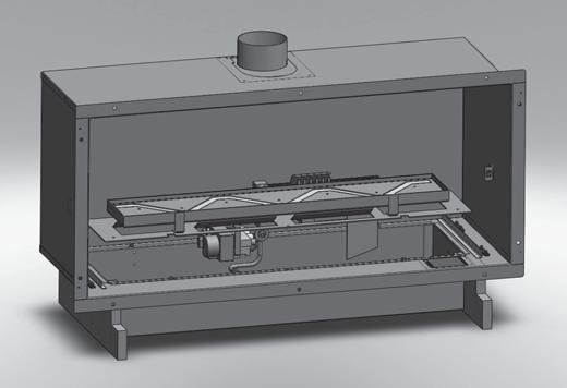
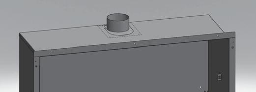
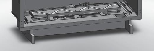


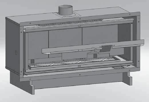

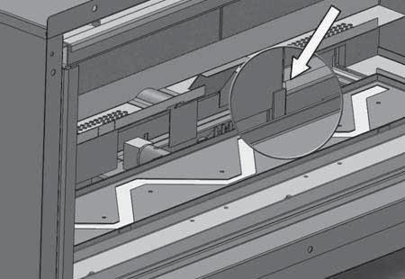
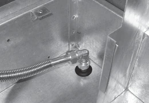
48 BIJLAGE 3 AFBEELDINGEN / APPENDIX 3 FIGURES 2 1 4a 4b 4c 4d 1 2 4e 4f 4g 4h 46
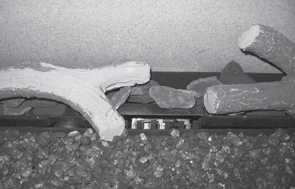


49 BIJLAGE 3 AFBEELDINGEN / APPENDIX 3 FIGURES 5a 5b 6a 6b 7 47


50 BIJLAGE 3 AFBEELDINGEN / APPENDIX 3 FIGURES 8a D A A A A B C E G G H H H F F 8b 8c 48
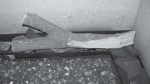


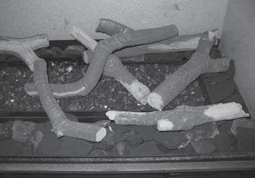


51 FIGURES 3 AFBEELDINGEN / APPENDIX 3 FIGURES 8d 8e 8f 8g 8h 8j 8k 49
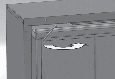


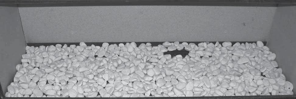

52 BIJLAGE 3 AFBEELDINGEN / APPENDIX 3 FIGURES 8m 9a 9b 10a 10b

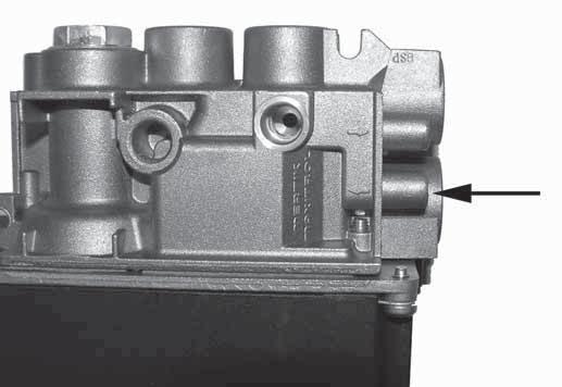

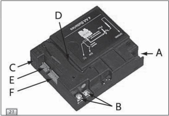
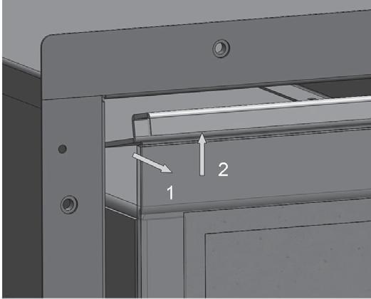

53 FIGURES 3 AFBEELDINGEN INSTALLATIEHANDLEIDING / APPENDIX 3 FIGURES 3 Nederlands 10c 10d 11a 11b


54 BIJLAGE 3 AFBEELDINGEN / APPENDIX 3 FIGURES
Nederlands. Gebruikershandleiding(NL/BE) voortoestellenmetwarmcv-wateroutput. Leesenbewaarditdocumentzorgvuldig nl
 voortoestellenmetwarmcv-wateroutput. Leesenbewaarditdocumentzorgvuldig nl") Gebruikershandleiding(NL/BE) voortoestellenmetwarmcv-wateroutput Leesenbewaarditdocumentzorgvuldig 958.015.00.nl NL Inhoudsopgave blz Woord vooraf 2 1. Inleiding 3 2. VEILIGHEID 3 2.1 Algemeen 3 2.2 Voorzorgsmaatregelen
Gebruikershandleiding(NL/BE) voortoestellenmetwarmcv-wateroutput Leesenbewaarditdocumentzorgvuldig 958.015.00.nl NL Inhoudsopgave blz Woord vooraf 2 1. Inleiding 3 2. VEILIGHEID 3 2.1 Algemeen 3 2.2 Voorzorgsmaatregelen
INSTALLATIEHANDLEIDING EN GEBRUIKERSHANDLEIDING (NL/BE) INSTALLATION MANUAL AND USER MANUAL (UK/IE) GLOBAL 70XT CF
 INSTALLATION MANUAL AND USER MANUAL (UK/IE) GLOBAL 70XT CF") INSTALLATIEHANDLEIDING EN GEBRUIKERSHANDLEIDING (NL/BE) INSTALLATION MANUAL AND USER MANUAL (UK/IE) GLOBAL 70XT CF Lees en bewaar dit document zorgvuldig Read this document and store it carefully DRU VERWARMING
INSTALLATIEHANDLEIDING EN GEBRUIKERSHANDLEIDING (NL/BE) INSTALLATION MANUAL AND USER MANUAL (UK/IE) GLOBAL 70XT CF Lees en bewaar dit document zorgvuldig Read this document and store it carefully DRU VERWARMING
Trio. Gebruikershandleiding (NL / BE) Nederlands. Lees en bewaar dit document zorgvuldig
 Nederlands. Lees en bewaar dit document zorgvuldig") Trio Gebruikershandleiding (NL / BE) Lees en bewaar dit document zorgvuldig NL 95800201NL Gebruik.indd 1 07-07-2008 09:23:23 Inhoudsopgave blz Woord vooraf 2 1. Inleiding 3 2. VEILIGHEID 3 2.1 Algemeen
Trio Gebruikershandleiding (NL / BE) Lees en bewaar dit document zorgvuldig NL 95800201NL Gebruik.indd 1 07-07-2008 09:23:23 Inhoudsopgave blz Woord vooraf 2 1. Inleiding 3 2. VEILIGHEID 3 2.1 Algemeen
Trio G20/G25. Installatiehandleiding (NL / BE) Nederlands. Bewaar dit document zorgvuldig
 Nederlands. Bewaar dit document zorgvuldig") Trio G20/G25 Installatiehandleiding (NL / BE) Bewaar dit document zorgvuldig NL Inhoudsopgave blz Woord vooraf 2 1. Inleiding 3 2. CE verklaring 3 3. VEILIGHEID 3 3.1 Algemeen 3 3.2 Voorschriften 3 3.3
Trio G20/G25 Installatiehandleiding (NL / BE) Bewaar dit document zorgvuldig NL Inhoudsopgave blz Woord vooraf 2 1. Inleiding 3 2. CE verklaring 3 3. VEILIGHEID 3 3.1 Algemeen 3 3.2 Voorschriften 3 3.3
INSTALLATIEHANDLEIDING EN GEBRUIKERSHANDLEIDING (NL/BE) INSTALLATION MANUAL AND USER MANUAL (GB/IE) GLOBAL 40 CF
 INSTALLATION MANUAL AND USER MANUAL (GB/IE) GLOBAL 40 CF") INSTALLATIEHANDLEIDING EN GEBRUIKERSHANDLEIDING (NL/BE) INSTALLATION MANUAL AND USER MANUAL (GB/IE) GLOBAL 40 CF Lees en bewaar dit document zorgvuldig Read this document and store it carefully DRU VERWARMING
INSTALLATIEHANDLEIDING EN GEBRUIKERSHANDLEIDING (NL/BE) INSTALLATION MANUAL AND USER MANUAL (GB/IE) GLOBAL 40 CF Lees en bewaar dit document zorgvuldig Read this document and store it carefully DRU VERWARMING
GLOBAL 40 CF GLOBAL BEAU CF
 INSTALLATIEHANDLEIDING EN GEBRUIKERSHANDLEIDING (NL/BE) INSTALLATION MANUAL AND USER MANUAL (GB/IE) GLOBAL 40 CF GLOBAL BEAU CF Lees en bewaar dit document zorgvuldig Read this document and store it carefully
INSTALLATIEHANDLEIDING EN GEBRUIKERSHANDLEIDING (NL/BE) INSTALLATION MANUAL AND USER MANUAL (GB/IE) GLOBAL 40 CF
 INSTALLATION MANUAL AND USER MANUAL (GB/IE) GLOBAL 40 CF") INSTALLATIEHANDLEIDING EN GEBRUIKERSHANDLEIDING (NL/BE) INSTALLATION MANUAL AND USER MANUAL (GB/IE) GLOBAL 40 CF Lees en bewaar dit document zorgvuldig Read this document and store it carefully DRU VERWARMING
INSTALLATIEHANDLEIDING EN GEBRUIKERSHANDLEIDING (NL/BE) INSTALLATION MANUAL AND USER MANUAL (GB/IE) GLOBAL 40 CF Lees en bewaar dit document zorgvuldig Read this document and store it carefully DRU VERWARMING
INSTALLATIEHANDLEIDING EN GEBRUIKERSHANDLEIDING (NL/BE) INSTALLATION MANUAL AND USER MANUAL (GB/IE)
 INSTALLATION MANUAL AND USER MANUAL (GB/IE)") INSTALLATIEHANDLEIDING EN GEBRUIKERSHANDLEIDING (NL/BE) INSTALLATION MANUAL AND USER MANUAL (GB/IE) Lees en bewaar dit document zorgvuldig Read this document and store it carefully DRU VERWARMING B.V.
INSTALLATIEHANDLEIDING EN GEBRUIKERSHANDLEIDING (NL/BE) INSTALLATION MANUAL AND USER MANUAL (GB/IE) Lees en bewaar dit document zorgvuldig Read this document and store it carefully DRU VERWARMING B.V.
Solo G20/G25. Installatiehandleiding (NL / BE) Nederlands. Bewaar dit document zorgvuldig
 Nederlands. Bewaar dit document zorgvuldig") Solo G20/G25 Installatiehandleiding ( / BE) Bewaar dit document zorgvuldig 95900605 Install_G20.indd 1 3-2-10 13:26 Inhoudsopgave blz Woord vooraf 2 1. Inleiding 3 2. CE verklaring 3 3. VEILIGHEID 3 3.1
Solo G20/G25 Installatiehandleiding ( / BE) Bewaar dit document zorgvuldig 95900605 Install_G20.indd 1 3-2-10 13:26 Inhoudsopgave blz Woord vooraf 2 1. Inleiding 3 2. CE verklaring 3 3. VEILIGHEID 3 3.1
INSTALLATIEHANDLEIDING EN GEBRUIKERSHANDLEIDING (NL/BE) INSTALLATION MANUAL AND USER MANUAL (GB/IE) GLOBAL 60i CF
 INSTALLATION MANUAL AND USER MANUAL (GB/IE) GLOBAL 60i CF") INSTALLATIEHANDLEIDING EN GEBRUIKERSHANDLEIDING (NL/BE) INSTALLATION MANUAL AND USER MANUAL (GB/IE) GLOBAL 60i CF Lees en bewaar dit document zorgvuldig Read this document and store it carefully DRU VERWARMING
INSTALLATIEHANDLEIDING EN GEBRUIKERSHANDLEIDING (NL/BE) INSTALLATION MANUAL AND USER MANUAL (GB/IE) GLOBAL 60i CF Lees en bewaar dit document zorgvuldig Read this document and store it carefully DRU VERWARMING
GLOBAL 100 BF G20/G25/G31
 INSTALLATIEHANDLEIDING EN GEBRUIKERSHANDLEIDING (NL/BE) INSTALLATION MANUAL AND USER MANUAL (GB/IE) GLOBAL 100 BF G20/G25/G31 Lees en bewaar dit document zorgvuldig Read this document and store it carefully
Gebruikershandleiding (NL/BE) voor toestellen uitgevoerd met elektronische ontsteking op de afstandsbediening. Nederlands
 voor toestellen uitgevoerd met elektronische ontsteking op de afstandsbediening. Nederlands") Gebruikershandleiding (NL/BE) voor toestellen uitgevoerd met elektronische ontsteking op de afstandsbediening Lees en bewaar dit document zorgvuldig 958.007.02.NL NL 95800702NL Gebruik.indd 1 8-6-10 9:35
Gebruikershandleiding (NL/BE) voor toestellen uitgevoerd met elektronische ontsteking op de afstandsbediening Lees en bewaar dit document zorgvuldig 958.007.02.NL NL 95800702NL Gebruik.indd 1 8-6-10 9:35
GLOBAL 70 GLOBAL 70 XT
 INSTALLATIEHANDLEIDING EN GEBRUIKERSHANDLEIDING (NL/BE) INSTALLATION MANUAL AND USER MANUAL (GB/IE) GLOBAL 70 GLOBAL 70 XT G20/G25 Lees en bewaar dit document zorgvuldig Read this document and store it
Largo - Largo Tunnel. Installatiehandleiding (NL / BE) Nederlands. Bewaar dit document zorgvuldig
 Nederlands. Bewaar dit document zorgvuldig") Largo - Largo Tunnel Installatiehandleiding ( / BE) Bewaar dit document zorgvuldig 95900902 Install_.indd 1 02-12-2008 15:31:16 Inhoudsopgave blz Woord vooraf 2 1. Inleiding 3 2. CE verklaring 3 3. VEILIGHEID
Largo - Largo Tunnel Installatiehandleiding ( / BE) Bewaar dit document zorgvuldig 95900902 Install_.indd 1 02-12-2008 15:31:16 Inhoudsopgave blz Woord vooraf 2 1. Inleiding 3 2. CE verklaring 3 3. VEILIGHEID
Gebruikershandleiding (NL/BE) voor toestellen uitgevoerd met elektronische ontsteking op de afstandsbediening. Nederlands
 voor toestellen uitgevoerd met elektronische ontsteking op de afstandsbediening. Nederlands") Gebruikershandleiding (NL/BE) voor toestellen uitgevoerd met elektronische ontsteking op de afstandsbediening Lees en bewaar dit document zorgvuldig 958.007.07.nl 1 NL Inhoudsopgave blz Woord vooraf 2
Gebruikershandleiding (NL/BE) voor toestellen uitgevoerd met elektronische ontsteking op de afstandsbediening Lees en bewaar dit document zorgvuldig 958.007.07.nl 1 NL Inhoudsopgave blz Woord vooraf 2
Metro 130 - Metro 130 Tunnel
 Metro 130 - Metro 130 Tunnel Installatiehandleiding (NL / BE) Bewaar dit document zorgvuldig 959.005.05.NL NL Inhoudsopgave blz Woord vooraf 2 1. Inleiding 3 2. CE verklaring 3 3. VEILIGHEID 3 3.1 Algemeen
Metro 100 XT Metro 100 XT Tunnel
 Metro 100 XT Metro 100 XT Tunnel Installatiehandleiding ( / BE) Bewaar dit document zorgvuldig 959.012.05. 95901205 Install_.indd 1 22-2-11 17:00 Inhoudsopgave Blz Woord vooraf 3 1. Inleiding 3 2. CE verklaring
Nederlands. Metro 100 XT-2 G20/25. Installatiehandleiding (NL / BE) Bewaar dit document zorgvuldig nl
 Bewaar dit document zorgvuldig nl") Metro 100 XT-2 G20/25 Installatiehandleiding (NL / BE) Bewaar dit document zorgvuldig 959.016.01.nl NL Inhoudsopgave Blz Woord vooraf 3 1. Inleiding 3 2. CE verklaring 3 3. VEILIGHEId 4 3.1 Algemeen 4
Metro 100 XT-2 G20/25 Installatiehandleiding (NL / BE) Bewaar dit document zorgvuldig 959.016.01.nl NL Inhoudsopgave Blz Woord vooraf 3 1. Inleiding 3 2. CE verklaring 3 3. VEILIGHEId 4 3.1 Algemeen 4
Gebruikshandleiding (NL / BE) Nederlands. Gebruikshandleiding voor toestellen uitgevoerd met elektronische ontsteking op de afstandsbediening
 Nederlands. Gebruikshandleiding voor toestellen uitgevoerd met elektronische ontsteking op de afstandsbediening") Gebruikshandleiding (NL / BE) Gebruikshandleiding voor toestellen uitgevoerd met elektronische ontsteking op de afstandsbediening Lees en bewaar dit document zorgvuldig NL GEBRU IKSHANDLEIDING Inhoudsopgave
Gebruikshandleiding (NL / BE) Gebruikshandleiding voor toestellen uitgevoerd met elektronische ontsteking op de afstandsbediening Lees en bewaar dit document zorgvuldig NL GEBRU IKSHANDLEIDING Inhoudsopgave
Metro 70 - Metro 70 Tunnel
 Metro 70 - Metro 70 Tunnel G31 Installatiehandleiding (NL / BE) Bewaar dit document zorgvuldig NL Inhoudsopgave blz Woord vooraf 2 1. Inleiding 3 2. CE verklaring 3 3. VEILIGHEID 3 3.1 Algemeen 3 3.2 Voorschriften
Saxo SL 80. Installatiehandleiding (NL / BE) Nederlands. Bewaar dit document zorgvuldig NL
 Nederlands. Bewaar dit document zorgvuldig NL") Saxo SL 80 Installatiehandleiding (NL / BE) Bewaar dit document zorgvuldig 959.010.02.NL NL Inhoudsopgave blz Woord vooraf 2 1. Inleiding 3 2. CE verklaring 3 3. VEILIGHEID 3 3.1 Algemeen 3 3.2 Voorschriften
Saxo SL 80 Installatiehandleiding (NL / BE) Bewaar dit document zorgvuldig 959.010.02.NL NL Inhoudsopgave blz Woord vooraf 2 1. Inleiding 3 2. CE verklaring 3 3. VEILIGHEID 3 3.1 Algemeen 3 3.2 Voorschriften
Nederlands. Cosmo - Cosmo Tunnel G20/G25. Installatiehandleiding (NL / BE) Bewaar dit document zorgvuldig NL
 Bewaar dit document zorgvuldig NL") Cosmo - Cosmo Tunnel G20/G25 Installatiehandleiding ( / BE) Bewaar dit document zorgvuldig 959.021.01. 95902101_ Install.indd 1 27-5-10 15:37 Inhoudsopgave blz Woord vooraf 3 1. Inleiding 3 2. CE verklaring
Cosmo - Cosmo Tunnel G20/G25 Installatiehandleiding ( / BE) Bewaar dit document zorgvuldig 959.021.01. 95902101_ Install.indd 1 27-5-10 15:37 Inhoudsopgave blz Woord vooraf 3 1. Inleiding 3 2. CE verklaring
Gebruikershandleiding. voor toestellen uitgevoerd met elektronische ontsteking op de afstandsbediening. Nederlands
 Gebruikershandleiding voor toestellen uitgevoerd met elektronische ontsteking op de afstandsbediening Lees en bewaar dit document zorgvuldig 958.007.08.nl 1 NL Inhoudsopgave blz Woord vooraf 2 1. Inleiding
Apollo 80. Installatiehandleiding (NL / BE) Nederlands. Bewaar dit document zorgvuldig NL
 Nederlands. Bewaar dit document zorgvuldig NL") Apollo 80 Installatiehandleiding (NL / BE) Bewaar dit document zorgvuldig 959.011.02.NL Inhoudsopgave blz Woord vooraf 2 1. Inleiding 3 2. CE verklaring 3 3. VEILIGHEID 3 3.1 Algemeen 3 3.2 Voorschriften
Apollo 80 Installatiehandleiding (NL / BE) Bewaar dit document zorgvuldig 959.011.02.NL Inhoudsopgave blz Woord vooraf 2 1. Inleiding 3 2. CE verklaring 3 3. VEILIGHEID 3 3.1 Algemeen 3 3.2 Voorschriften
Nederlands. Gebruikershandleiding(NL/BE) voortoestellenmeteenhoneywell-afstandsbediening. Leesenbewaarditdocumentzorgvuldig. 958.016.02.
 voortoestellenmeteenhoneywell-afstandsbediening. Leesenbewaarditdocumentzorgvuldig. 958.016.02.") Gebruikershandleiding(NL/BE) voortoestellenmeteenhoneywell-afstandsbediening Leesenbewaarditdocumentzorgvuldig 958.016.02.nl 1 NL Inhoud blz Woordvooraf 3 1. Inleiding 4 2. VEILIGHEID 4 2.1Algemeen 4 2.2Voorzorgsmaatregelen/veiligheidsinstructies
Gebruikershandleiding(NL/BE) voortoestellenmeteenhoneywell-afstandsbediening Leesenbewaarditdocumentzorgvuldig 958.016.02.nl 1 NL Inhoud blz Woordvooraf 3 1. Inleiding 4 2. VEILIGHEID 4 2.1Algemeen 4 2.2Voorzorgsmaatregelen/veiligheidsinstructies
Nederlands. Milo G20/G25/G31. Installatiehandleiding (NL / BE) NL. Bewaar dit document zorgvuldig
 NL. Bewaar dit document zorgvuldig") Milo G20/G25/G31 Installatiehandleiding ( / BE) Bewaar dit document zorgvuldig 959.028.01. 95902801_ Install.indd 1 12-7-10 10:33 Inhoudsopgave Blz Woord vooraf 3 1. Inleiding 3 2. CE verklaring 4 3. VEILIGHEID
Milo G20/G25/G31 Installatiehandleiding ( / BE) Bewaar dit document zorgvuldig 959.028.01. 95902801_ Install.indd 1 12-7-10 10:33 Inhoudsopgave Blz Woord vooraf 3 1. Inleiding 3 2. CE verklaring 4 3. VEILIGHEID
Trio. G20/G25/G25.3 (aardgas) Installatiehandleiding (NL / BE) Nederlands. Bewaar dit document zorgvuldig. 959.064.02.nl
 Installatiehandleiding (NL / BE) Nederlands. Bewaar dit document zorgvuldig. 959.064.02.nl") Trio G20/G25/G25.3 (aardgas) Installatiehandleiding (NL / BE) Bewaar dit document zorgvuldig 959.064.02.nl NL Inhoudsopgave blz Woord vooraf 2 1. Inleiding 3 2. CE verklaring 3 3. VEILIGHEID 3 3.1 Algemeen
Trio G20/G25/G25.3 (aardgas) Installatiehandleiding (NL / BE) Bewaar dit document zorgvuldig 959.064.02.nl NL Inhoudsopgave blz Woord vooraf 2 1. Inleiding 3 2. CE verklaring 3 3. VEILIGHEID 3 3.1 Algemeen
Global 100 BF-03. G20/G25/G25.3 (Aardgas) G31 (Propaan) Installatiehandleiding (NL/BE) Nederlands. Bewaar dit document zorgvuldig
 G31 (Propaan) Installatiehandleiding (NL/BE) Nederlands. Bewaar dit document zorgvuldig") Global 100 F-03 G20/G25/G25.3 (ardgas) G31 (Propaan) 38P-0574 Installatiehandleiding (/E) ewaar dit document zorgvuldig 959.095.01. DRU-675446---1115-3 INSTLLTIEHNDLEIDING Inhoud 1. Inleiding 2. E-verklaring
Global 100 F-03 G20/G25/G25.3 (ardgas) G31 (Propaan) 38P-0574 Installatiehandleiding (/E) ewaar dit document zorgvuldig 959.095.01. DRU-675446---1115-3 INSTLLTIEHNDLEIDING Inhoud 1. Inleiding 2. E-verklaring
Nederlands. Gebruikershandleiding(NL/BE) voortoestellenmeteenhoneywell-afstandsbediening. Leesenbewaarditdocumentzorgvuldig
 voortoestellenmeteenhoneywell-afstandsbediening. Leesenbewaarditdocumentzorgvuldig") Gebruikershandleiding(NL/BE) voortoestellenmeteenhoneywell-afstandsbediening Leesenbewaarditdocumentzorgvuldig 958.016.00.nl 1 NL Inhoudsopgave blz Woord vooraf 3 1. Inleiding 4 2. VEILIGHEID 4 2.1 Algemeen
Gebruikershandleiding(NL/BE) voortoestellenmeteenhoneywell-afstandsbediening Leesenbewaarditdocumentzorgvuldig 958.016.00.nl 1 NL Inhoudsopgave blz Woord vooraf 3 1. Inleiding 4 2. VEILIGHEID 4 2.1 Algemeen
Gasblokkenvuur serie - handbediening. Installatievoorschrift Gebruiksaanwijzing
 Gasblokkenvuur 2000 serie - handbediening Installatievoorschrift Gebruiksaanwijzing REAL FIRE GASBLOKKENVUUR Installatievoorschrift Inleiding : Lees voor het installeren van het blokkenvuur deze gebruiksaanwijzing
Metro 80XT Metro 80XT Tunnel
 Metro 80XT Metro 80XT Tunnel G20/G25/G31 Installatiehandleiding (/E) ewaar dit document zorgvuldig 959.036.02 DRU12638-29208---0213-4 INSTLLTIEHNDLEIDING Inhoud 1. Inleiding 2. E-verklaring 3. VEILIGHEID
Excellence XT G20/G25. Installatiehandleiding (NL/BE) Nederlands. Bewaar dit document zorgvuldig 959.045.00NL DRU131490-186075-NL-NL-0912-1
 Nederlands. Bewaar dit document zorgvuldig 959.045.00NL DRU131490-186075-NL-NL-0912-1") Excellence XT G20/G25 Installatiehandleiding (/E) ewaar dit document zorgvuldig 959.045.00 DRU131490-186075---0912-1 INSTLLTIEHNDLEIDING Inhoudsopgave 1. Inleiding 2. E-verklaring 3. VEILIGHEID 3.1 lgemeen
Excellence XT G20/G25 Installatiehandleiding (/E) ewaar dit document zorgvuldig 959.045.00 DRU131490-186075---0912-1 INSTLLTIEHNDLEIDING Inhoudsopgave 1. Inleiding 2. E-verklaring 3. VEILIGHEID 3.1 lgemeen
Installatievoorschrift en gebruikershandleiding PRIMO TRENTO. Bewaar deze gebruikershandleiding zorgvuldig! DRU VERWARMING HOLLAND 957479-1
 Installatievoorschrift en gebruikershandleiding PRIMO TRENTO Bewaar deze gebruikershandleiding zorgvuldig! DRU VERWARMING HOLLAND 957479-1 Inhoud Pagina 3. Woord vooraf Geachte klant Verpakking Installatievoorschrift
Metro 130 XT Metro 130 XT Tunnel
 Metro 130 XT Metro 130 XT Tunnel G20/G25/G31 Installatiehandleiding (/E) ewaar dit document zorgvuldig 959.041.00. DRU12638-101386---0112-2 INSTLLTIEHNDLEIDING Inhoud 1. Inleiding 2. E-verklaring 3. VEILIGHEID
Gebruikers- en installatie- handleiding SUNWOOD MARINO. Propaan
 Gebruikers- en installatie- handleiding SUNWOOD MARINO Versie: Aardgas Propaan Specificaties Fabrikant Sunderman Openhaarden V.O.F. / Sunwood Contactgegevens Christiaan Huygensstraat 10 2665 KX Bleiswijk
Addendum installatiehandleiding CM toestellen.
 Addendum installatiehandleiding CM toestellen. Let op! Indien het toestel is uitgevoerd met het CM systeem, zijn de onderstaande hoofdstukken en paragraven van toepassing, i.p.v. de hoofdstukken en paragraven
Gebruikershandleiding (NL/BE) voor toestellen met een Honeywell-afstandsbediening. Nederlands. Lees en bewaar dit document zorgvuldig 1 NL
 voor toestellen met een Honeywell-afstandsbediening. Nederlands. Lees en bewaar dit document zorgvuldig 1 NL") Gebruikershandleiding (NL/BE) voor toestellen met een Honeywell-afstandsbediening Lees en bewaar dit document zorgvuldig 958.016.03.nl 1 NL Inhoud blz Woord vooraf 3 1. Inleiding 4 2. VEILIGHEID 4 2.1
Gebruikershandleiding (NL/BE) voor toestellen met een Honeywell-afstandsbediening Lees en bewaar dit document zorgvuldig 958.016.03.nl 1 NL Inhoud blz Woord vooraf 3 1. Inleiding 4 2. VEILIGHEID 4 2.1
Installatievoorschrift en Gebruikershandleiding FOX. Bewaar dit document zorgvuldig DRU VERWARMING B.V. HOLLAND
 Installatievoorschrift en Gebruikershandleiding FOX Bewaar dit document zorgvuldig DRU VERWARMING B.V. HOLLAND 957506 Maatschets Fox 2 Woord vooraf Geachte klant, Vriendelijk bedankt voor de aankoop van
The Tube Installatie- en gebruikersvoorschrift
 The Tube 40011124-1125 NL Installatie- en gebruikersvoorschrift NL 1.1A 1.1B 1.1C 1.2A 1.2B 1.2C 1 < < < < 1.3 1.4 1.5 1.6 1.7 2 < < < < 1 Inleiding We adviseren dringend deze installatie en gebruikersvoorschriften
Trio. G31 Propaan. Installatiehandleiding (NL / BE) Nederlands. Bewaar dit document zorgvuldig NL
 Nederlands. Bewaar dit document zorgvuldig NL") Trio G31 Propaan Installatiehandleiding (NL / BE) Bewaar dit document zorgvuldig 959.065.01.NL NL Inhoudsopgave blz Woord vooraf 2 1. Inleiding 3 2. CE verklaring 3 3. VEILIGHEID 3 3.1 Algemeen 3 3.2 Voorschriften
Trio G31 Propaan Installatiehandleiding (NL / BE) Bewaar dit document zorgvuldig 959.065.01.NL NL Inhoudsopgave blz Woord vooraf 2 1. Inleiding 3 2. CE verklaring 3 3. VEILIGHEID 3 3.1 Algemeen 3 3.2 Voorschriften
Agua F100 - Agua B100
 Agua F100 - Agua B100 G20/G25/G31 Installatiehandleiding (/BE) Bewaar dit document zorgvuldig 95903301 DRU47627-48460---0112-3 Inhoudsopgave 1. Inleiding 2. CE-verklaring 3. VEILIGHEID 3.1 Algemeen 3.2
Gasblokkenvuur. RF - TT - Tiptronic. Installatievoorschrift Gebruiksaanwijzing
 Gasblokkenvuur RF - TT - Tiptronic Installatievoorschrift Gebruiksaanwijzing REAL FIRE GASBLOKKENVUUR Installatievoorschrift: Tiptronic RF / TT - serie Inleiding : Lees voor het installeren van het blokkenvuur
BAMBINO 70T BAMBINO 46T
 40010546-0415 BAMBINO 70T BAMBINO 46T 7.3 Onderhoud NL NL INHOUDSOPGAVE 1. VOORWOORD 2 2. INLEIDING 3 3. VEILIGHEIDSAANWIJZINGEN 4 4. VOORBEREIDING EN PLAATSING VAN DE HAARD 6 4.1 Gasaansluiting 6 4.2
Gebruikers Handleiding
 Gebruikers Handleiding Woord vooraf Inhoud Uw Salamander gashaard is voorzien van een CE-merk. Alleen hoog rendement gesloten gashaarden die voldoen aan de strengste Europese eisen voor veiligheid, milieu
4 Knops afstandsbediening
 Lees en bewaar dit document zorgvuldig! Installatie instructies Gebruikershandleiding 4 Knops afstandsbediening Well Straler Industrielaan 22 9320 Erembodegem info@wellstraler.be www.wellstraler.be Inhoudstafel
Milo. G20/G25 (Aardgas) G31 (Propaan) Installatiehandleiding (NL/BE) Nederlands. Bewaar dit document zorgvuldig NL
 G31 (Propaan) Installatiehandleiding (NL/BE) Nederlands. Bewaar dit document zorgvuldig NL") Milo G20/G25 (ardgas) G31 (Propaan) Installatiehandleiding (/B) Bewaar dit document zorgvuldig 959.028.03. 959.028.04. INSTLLTIHNDLIDING Inhoud 1. Inleiding 2. -verklaring 3. VILIGHID 3.1 lgemeen 3.2 Voorschriften
Milo G20/G25 (ardgas) G31 (Propaan) Installatiehandleiding (/B) Bewaar dit document zorgvuldig 959.028.03. 959.028.04. INSTLLTIHNDLIDING Inhoud 1. Inleiding 2. -verklaring 3. VILIGHID 3.1 lgemeen 3.2 Voorschriften
Gasblokkenvuur. RF - E serie : electronic. Installatievoorschrift Gebruiksaanwijzing
 Gasblokkenvuur RF - E serie : electronic Installatievoorschrift Gebruiksaanwijzing REAL FIRE Gasblokkenvuren Installatievoorschrift : RF/E - serie Inleiding. Lees voor het installeren van het blokkenvuur
INSTALLATIEVOORSCHRIFTEN EN GEBRUIKSAANWIJZING
 IXA-BELL ZONDER ROOKKANAAL en SLIM-BELL ZONDER ROOKKANAAL INSTALLATIEVOORSCHRIFTEN EN GEBRUIKSAANWIJZING Dit document na installatie bij klant afgeven Waarschuwing De verbrandingskamer van deze haard mag
Excellence 70. G20/G25 Aardgas. Installatiehandleiding (NL/BE) Nederlands. Bewaar dit document zorgvuldig DRU131490-142717-NL-NL-1113-6 959.042.03.
 Nederlands. Bewaar dit document zorgvuldig DRU131490-142717-NL-NL-1113-6 959.042.03.") Excellence 70 G20/G25 ardgas Installatiehandleiding (/E) ewaar dit document zorgvuldig 959.042.03. DRU131490-142717---1113-6 INSTLLTIEHNDLEIDING Inhoudsopgave 1. Inleiding 2. E-verklaring 3. VEILIGHEID
Excellence 70 G20/G25 ardgas Installatiehandleiding (/E) ewaar dit document zorgvuldig 959.042.03. DRU131490-142717---1113-6 INSTLLTIEHNDLEIDING Inhoudsopgave 1. Inleiding 2. E-verklaring 3. VEILIGHEID
The Buzz 40010883-1020. Installatie- en gebruikersvoorschrift
 The Buzz 40010883-1020 NL Installatie- en gebruikersvoorschrift NL 1.1 A 1.3 1.4 B 1.5 1.6 1 < < < < D 1.7 1.8 1 2.1 2.2 3.1 3.2 3.3 2 < < < < Inhoudsopgave 1 Inleiding... 4 2 Veiligheidsaanwijzingen....
Long-fire branders. RFL E electronic. Installatievoorschrift Gebruiksaanwijzing
 Long-fire branders RFL E electronic Installatievoorschrift Gebruiksaanwijzing REAL FIRE GASBLOKKENVUUR Installatievoorschrift RFL - E Inleiding : Lees voor het installeren van het blokkenvuur deze gebruiksaanwijzing
Trio RCE. G20/G25/G25.3 (aardgas) Installatiehandleiding. Nederlands. Bewaar dit document zorgvuldig NL
 Installatiehandleiding. Nederlands. Bewaar dit document zorgvuldig NL") Trio RCE G20/G25/G25.3 (aardgas) Installatiehandleiding Bewaar dit document zorgvuldig 959.064.03.NL NL Inhoudsopgave blz Woord vooraf 2 1. Inleiding 3 2. CE verklaring 3 3. VEILIGHEID 3 3.1 Algemeen 3
Trio RCE G20/G25/G25.3 (aardgas) Installatiehandleiding Bewaar dit document zorgvuldig 959.064.03.NL NL Inhoudsopgave blz Woord vooraf 2 1. Inleiding 3 2. CE verklaring 3 3. VEILIGHEID 3 3.1 Algemeen 3
GEBRUIKERS HANDLEIDING INBOUWSTAPELAARS
 1 GEBRUIKERS HANDLEIDING INBOUWSTAPELAARS 2 INHOUD 1. REGISTRATIE SERIENUMMERS 2. INLEIDING 3. BESCHRIJVING VAN DE STAPELAAR 4. WERKING VAN DE STAPELAAR 5. INSTALLEREN VAN DE STAPELAAR 6. GEBRUIKEN VAN
Montagehandleiding aardgas types
 Montagehandleiding aardgas types INHOUDSOPGAVE bladzijde Installatie & bedieningshandleiding 2 Gebruikershandleiding 4 Verklarende afbeeldingen 5 Installatie instructies type GS9, GS10 en GS11 6 Installatie
Rolkachel infrarood Chauffage mobile infrarouge Gasheizung Mobil infrarot Mobile gasheater infrared. Model: GRT-508
 Rolkachel infrarood Chauffage mobile infrarouge Gasheizung Mobil infrarot Mobile gasheater infrared Model: GRT-508 Handleiding Mode d emploi Gebrauchsanweisung Manual Lees deze handleiding aandachtig door
Gebruikers- en installatie handleiding GVK 5 DL GVK 7 DL GVK 3 GVK 5 GVK 7. Laat deze instructies als handleiding achter bij het toestel
 Gebruikers- en installatie handleiding GVK 5 DL GVK 7 DL GVK 3 GVK 5 GVK 7 Let op: de verbrandingskamer van deze gashaard mag uitsluitend worden geopend en onderhouden door een bekwaam gasinstallateur
Gebruikershandleiding (NL/BE) voor toestellen met een Honeywell-afstandsbediening. Nederlands. Lees en bewaar dit document zorgvuldig 1 NL
 voor toestellen met een Honeywell-afstandsbediening. Nederlands. Lees en bewaar dit document zorgvuldig 1 NL") Gebruikershandleiding (NL/BE) voor toestellen met een Honeywell-afstandsbediening Lees en bewaar dit document zorgvuldig 958.016.05.nl 1 NL Inhoud blz Woord vooraf 3 1. Inleiding 4 2. VEILIGHEID 4 2.1
Gebruikershandleiding (NL/BE) voor toestellen met een Honeywell-afstandsbediening Lees en bewaar dit document zorgvuldig 958.016.05.nl 1 NL Inhoud blz Woord vooraf 3 1. Inleiding 4 2. VEILIGHEID 4 2.1
Milo Small G20/G25/G31. Installatiehandleiding (NL/BE) Nederlands. Bewaar dit document zorgvuldig DRU NL-NL
 Nederlands. Bewaar dit document zorgvuldig DRU NL-NL") Milo Small G20/G25/G31 Installatiehandleiding (/E) ewaar dit document zorgvuldig 959.030.03. DRU46686-125526---0113-4 INSTLLTIEHNDLEIDING Inhoud 1. Inleiding 2. E-verklaring 3. VEILIGHEID 3.1 lgemeen 3.2
Milo Small G20/G25/G31 Installatiehandleiding (/E) ewaar dit document zorgvuldig 959.030.03. DRU46686-125526---0113-4 INSTLLTIEHNDLEIDING Inhoud 1. Inleiding 2. E-verklaring 3. VEILIGHEID 3.1 lgemeen 3.2
Model EF-2000W Handleiding
 Thermic Dynamics Eco Class Heater Model EF-2000W Handleiding Waarschuwingen Dit apparaat is bedoeld voor gebruik in huishoudens en dient niet gebruikt te worden voor andere doeleinden, zoals in een niet-huiselijke
Lees en bewaar dit document zorgvuldig! Installatie instructies Gebruikershandleiding 10 Knops afstandsbediening
 Lees en bewaar dit document zorgvuldig! Installatie instructies Gebruikershandleiding 10 Knops afstandsbediening Well Straler Industrielaan 22 9320 Erembodegem info@wellstraler.be www.wellstraler.be Inhoudstafel
Maestro 80-2 RCH Maestro 80-3 RCH
 Maestro 80-2 RH Maestro 80-3 RH G20/G25/G25.3 (ardgas) G31 (Propaan) Installatiehandleiding (/E) ewaar dit document zorgvuldig 959.094.03. DRU-676614---0116-5 INSTLLTIEHNDLEIDING Inhoudsopgave 1. Inleiding
ABSORPTIE KOELKAST MODEL FA60G 12 V - 220/230 V - Flessengas GEBRUIKSAANWIJZING
 e x q u i s i t ABSORPTIE KOELKAST MODEL FA60G 12 V - 220/230 V - Flessengas GEBRUIKSAANWIJZING DOMEST Import-Export b.v. J.F. Kennedylaan 101b NL7001CZ Doetinchem www.domest.com Lees deze gebruiksaanwijzing
GEBRUIKSAANWIJZING RIJSTKOKER Modelnr.: *688.087
 Professional Supplies GEBRUIKSAANWIJZING RIJSTKOKER Modelnr.: *688.087 Afbeelding alleen ter illustratie, specificaties zijn afhankelijk van het werkelijke product. Lees voor het gebruik zorgvuldig de
INHOUDSOPGAVE BELANGRIJKE VEILIGHEIDSINFORMATIE... 6
 INHOUDSOPGAVE BEDIENINGSHANDLEIDING Algemene opmerkingen... 1 Afstemmen zender / ontvanger... 1 Toestel inschakelen... 2 Toestel uitschakelen... 2 Afstelling vlamhoogte... 2 Bediening van de circulatieventilator...
DRU-ART 2 DRU-ART 3 DRU-ART 4 DRU-ART 5 DRU-ART 6 DRU-ART 8-01 DRU-ART 10-01
 INSTALLATIEVOORSCHRIFT EN GEBRUIKERSHANDLEIDING NL/BE DRU-ART 2 DRU-ART 3 DRU-ART 4 DRU-ART 5 DRU-ART 6 DRU-ART 8-01 DRU-ART 10-01 Bewaar dit document zorgvuldig DRU VERWARMING B.V. HOLLAND 957.505.07
AANWIJZINGEN VOOR DE INSTALLATIE
 10200177NL.fm Page 19 Wednesday, June 29, 2005 4:30 PM AANWIJZINGEN VOOR DE INSTALLATIE ALVORENS DE KOELKAST TE INSTALLEREN...20 ALGEMENE VOORZORGSMAATREGELEN EN ADVIEZEN...20 WATERAANSLUITING...21 ELEKTRISCHE
GEBRUIKSAANWIJZING WAND AFZUIGKAPPEN
 GEBRUIKSAANWIJZING WAND AFZUIGKAPPEN 2 GARANTIE Op het apparaat is 24 maanden garantie vanaf koopdatum. Uitgesloten van garantie zijn: verlichting, schade en gevolgschade ontstaan door een gebrekkig gemonteerde
STORINGSHANDLEIDING GASGESTOOKTE LUCHTVERWARMERS
 STORINGSHANDLEIDING GASGESTOOKTE LUCHTVERWARMERS BOUWJAAR 2000-2004 URA-20 URA-25 URA-35 URA-45 URA-55 URA-65 URA-80 URA-95 Werking Voor men begint met de in bedrijfstelling is het raadzaam te controleren
ALVORENS DE KOOKPLAAT TE GEBRUIKEN Blz. 19. ADVIEZEN VOOR MILIEUBESCHERMING Blz. 19. WAARSCHUWINGEN EN ALGEMENE WENKEN Blz. 19
 NL INHOUD ALVORENS DE KOOKPLAAT TE GEBRUIKEN Blz. 19 ADVIEZEN VOOR MILIEUBESCHERMING Blz. 19 WAARSCHUWINGEN EN ALGEMENE WENKEN Blz. 19 ADVIEZEN VOOR ENERGIEBESPARING Blz. 20 REINIGING EN ONDERHOUD VAN
Gebruikershandleiding (NL/BE) voor toestellen met een Honeywell-afstandsbediening. Nederlands. Lees en bewaar dit document zorgvuldig 1 NL
 voor toestellen met een Honeywell-afstandsbediening. Nederlands. Lees en bewaar dit document zorgvuldig 1 NL") Gebruikershandleiding (NL/BE) voor toestellen met een Honeywell-afstandsbediening Lees en bewaar dit document zorgvuldig 958.016.07.nl 1 NL Inhoud blz Woord vooraf 3 1. Inleiding 4 2. VEILIGHEID 4 2.1
Gebruikershandleiding (NL/BE) voor toestellen met een Honeywell-afstandsbediening Lees en bewaar dit document zorgvuldig 958.016.07.nl 1 NL Inhoud blz Woord vooraf 3 1. Inleiding 4 2. VEILIGHEID 4 2.1
Montage handleiding Broilfire 4 Poot powerfire/gas komfoor 4p-01p
 Montage handleiding Broilfire 4 Poot powerfire/gas komfoor 4p-01p Instructies voor het monteren en gebruik van de Powerfire: Technische data: Gas type Butaan Propaan Werk druk: mbar 30-50 37-52 Categorie
Skive Installatievoorschrift
 Skive 40011127-1113 skive 40011127-1113 N Installatievoorschrift N 1.1 1.2 1.3 1.4 1 < < < < 1.5 1.6 1.7 1.8 1.9 2 < < < < 1 Inleiding kinderen en huisdieren niet in de ruimte aanwezig zijn. De haard mag
Gumax Terrasverwarmer
 Gumax Terrasverwarmer De energiezuinige terrasverwarmer op infraroodbasis zonder rode gloed Handleiding Model PAH-2011-1 3200 watt Lees alle instructies zorgvuldig door alvorens dit apparaat te installeren
HOOFDVRIJE AFZUIGKAPPEN
 GEBRUIKSAANWIJZING HOOFDVRIJE AFZUIGKAPPEN 2 GARANTIE Op het apparaat is 24 maanden garantie vanaf koopdatum. Uitgesloten van garantie zijn: verlichting, schade en gevolgschade ontstaan door een gebrekkig
Handleiding FUGA S. wijzigingen voorbehouden december 2005
 Handleiding NL FUGA S wijzigingen voorbehouden december 2005 2 Wij feliciteren u met de aanschaf van uw Fuga S SwingGaz. Met deze handleiding willen wij u graag informeren over een juist gebruik van de
GEBRUIKSAANWIJZING v. 1.0 AFR-060 FITTING-ONTVANGER
 GEBRUIKSAANWIJZING v. 1.0 AFR-060 FITTING-ONTVANGER A B C * Verlichting: Aan / Uit * Afbeelding van de YCT-102 (niet inbegrepen) A: Fitting voor gloeilamp B: Zoekmode-knop C: Indicator 1 [1] Uitschakelen
Hoofdmaten V2xx-xxALU-x, V3xx-xxALU-x. Met LED en LED-schakelaar. Cilinder: 17 mm Europrofiel. Benodigdheden
 Handleiding Montage V25x-xxRVS-x/V25x-xxALU-x smalschild V35x-xxRVS-x/V35x-xxALU-x breedschild Waarschuwingen! Alle voorzorgsmaatregelen, instructies en waarschuwingen zoals beschreven in de handleiding
Nederlands. PowerVent. Installatiehandleiding (NL / BE) Bewaar dit document zorgvuldig NL
 Bewaar dit document zorgvuldig NL") PowerVent Installatiehandleiding (NL / BE) Bewaar dit document zorgvuldig 959.034.04.NL NL Inhoudsopgave Blz Woord vooraf 3 1. Inleiding 3 2. CE verklaring 4 3. VEILIGHEId 4 3.1 Algemeen 4 3.2 Voorschriften
PowerVent Installatiehandleiding (NL / BE) Bewaar dit document zorgvuldig 959.034.04.NL NL Inhoudsopgave Blz Woord vooraf 3 1. Inleiding 3 2. CE verklaring 4 3. VEILIGHEId 4 3.1 Algemeen 4 3.2 Voorschriften
Gefeliciteerd met uw nieuwe autoalarm! Inhoud
 Gefeliciteerd met uw nieuwe autoalarm! Lees de gebruikershandleiding voor gebruik zorgvuldig door en maak u vertrouwd met de verschillende functies van uw autoalarm. Deze handleiding beschrijft de functies
Excellence M. G20/G25 Aardgas. Installatiehandleiding (NL/BE) Nederlands. Bewaar dit document zorgvuldig NL DRU NL-NL
 Nederlands. Bewaar dit document zorgvuldig NL DRU NL-NL") Excellence M G20/G25 ardgas Installatiehandleiding (/E) ewaar dit document zorgvuldig 959.043.03 DRU131490-145656---0513-4 Inhoudsopgave 1. Inleiding 2. E-verklaring 3. VEILIGHEID 3.1 lgemeen 3.2 Voorschriften
Excellence M G20/G25 ardgas Installatiehandleiding (/E) ewaar dit document zorgvuldig 959.043.03 DRU131490-145656---0513-4 Inhoudsopgave 1. Inleiding 2. E-verklaring 3. VEILIGHEID 3.1 lgemeen 3.2 Voorschriften
AANWIJZINGEN VOOR DE INSTALLATIE
 SbS_Inst_102_00286_NL 23-04-2007 10:43 Pagina 20 AANWIJZINGEN VOOR DE INSTALLATIE ALVORENS DE KOELKAST TE INSTALLEREN WATERAANSLUITING ELEKTRISCHE AANSLUITING NIVELLEREN VAN DE KOELKAST INSTALLATIE VAN
Excellence XT. G20/G25 Aardgas. Installatiehandleiding (NL/BE) Nederlands. Bewaar dit document zorgvuldig NL DRU NL-NL
 Nederlands. Bewaar dit document zorgvuldig NL DRU NL-NL") Excellence XT G20/G25 ardgas Installatiehandleiding (/E) ewaar dit document zorgvuldig 959.045.02 DRU131490-186075---0513-3 INSTLLTIEHNDLEIDING Inhoudsopgave 1. Inleiding 2. E-verklaring 3. VEILIGHEID
Excellence XT G20/G25 ardgas Installatiehandleiding (/E) ewaar dit document zorgvuldig 959.045.02 DRU131490-186075---0513-3 INSTLLTIEHNDLEIDING Inhoudsopgave 1. Inleiding 2. E-verklaring 3. VEILIGHEID
Gebruikers- en installatie handleiding (NL/BE) Cupido 50, Cupido 70, Optica, Bioptica. Laat deze instructies als handleiding achter bij het toestel
 Cupido 50, Cupido 70, Optica, Bioptica. Laat deze instructies als handleiding achter bij het toestel") Gebruikers- en installatie handleiding (NL/BE) Cupido 50, Cupido 70, Optica, Bioptica Let op: de verbrandingskamer van deze gashaard mag uitsluitend worden geopend en onderhouden door een bekwaam gasinstallateur
Gebruikers- en installatie handleiding (NL/BE) Cupido 50, Cupido 70, Optica, Bioptica Let op: de verbrandingskamer van deze gashaard mag uitsluitend worden geopend en onderhouden door een bekwaam gasinstallateur
Gebruikershandleiding (NL/BE) voor toestellen met een Honeywell-afstandsbediening. Nederlands. Lees en bewaar dit document zorgvuldig 1 NL
 voor toestellen met een Honeywell-afstandsbediening. Nederlands. Lees en bewaar dit document zorgvuldig 1 NL") Gebruikershandleiding (NL/BE) voor toestellen met een Honeywell-afstandsbediening Lees en bewaar dit document zorgvuldig 958.016.08.nl 1 NL Inhoud blz Woord vooraf 3 1. Inleiding 4 2. VEILIGHEID 4 2.1
Gebruikershandleiding (NL/BE) voor toestellen met een Honeywell-afstandsbediening Lees en bewaar dit document zorgvuldig 958.016.08.nl 1 NL Inhoud blz Woord vooraf 3 1. Inleiding 4 2. VEILIGHEID 4 2.1
AGDR-300 TUIN STEKKERDOOS DIMMER/SCHAKELAAR. 2x 3x
 2x 3x [5] De stekkerdoos schakelt ter bevestiging 2x in en uit. De code van de zender is in het geheugen van de stekkerdoos opgeslagen en het product is klaar voor gebruik. Er kunnen maximaal 6 verschillende
Nederlands. PowerVent Installatiehandleiding. Bewaar dit document zorgvuldig NL
 PowerVent - 01 Installatiehandleiding Bewaar dit document zorgvuldig 959.106.00.NL nl Inhoudsopgave Blz Woord vooraf 3 1. Inleiding 3 2. CE verklaring 4 3. VEILIGHEID 4 3.1 Algemeen 4 3.2 Voorschriften
Afzuigkap Gebruiksaanwijzing
 Afzuigkap Gebruiksaanwijzing Inhoudsopgave 1.Opmerkingen 2.Functies 3..Installatie 4..Opmerkingen over installatie 5..Veiligheidswaarschuwingen 6 Gebruik 7 Onderhoud 1 Opmerkingen 1. Bedankt voor het kiezen
Packard Bell Easy Repair
 Packard Bell Easy Repair EasyNote MZ serie Instructies voor het vervangen van geheugenmodules 7429180005 7429180005 Documentversie: 1.0 - Mei 2007 www.packardbell.com Belangrijke veiligheidsinstructies
Quattro-fire Gasblokken
 Quattro-fire Gasblokken Quattro-fire 20 x 20 Quattro-fire 35 x 20 Quattro-fire 50 x 20 Quattro-fire 65 x 20 Quattro-fire 80 x 20 Quattro-fire 100 x 20 Quattro-fire 120 x 20 Quattro-fire 140 x 20 Quattro-fire
Gebruiksaanwijzing RTW100
 Gebruiksaanwijzing RTW100 Inhoudsopgave Technische gegevens Beschrijving apparaat Elektrische aansluiting Installatie en adviezen Beschrijving bedieningspaneel De eerste keer Adviezen Storingen en mogelijke
GEBRUIKSAANWIJZING v. 1.1 AC-1000 STEKKERDOOSSCHAKELAAR
 GEBRUIKSAANWIJZING v. 1.1 AC-1000 STEKKERDOOSSCHAKELAAR A B C * Verlichting: Aan / Uit * Afbeelding van de YCT-102 (niet altijd inbegrepen, check de specificaties op de verpakking) A: Indicator (spannings-
Gebruiksaanwijzing. Gasbranders. 057.130.7 Gasbrander zonder vlambeveiliging 057.131.7-057.146.3 Gasbranders met vlambeveiliging.
 Gasbranders Overzicht 057.130.7 gasbrander 20cm, butaan/propaan, 5 kw, zonder vlambeveiliging 057.131.5 gasbrander 30cm, butaan/propaan, 7 kw + vlambeveiliging 057.132.3 gasbrander 40cm, butaan/propaan,
Gumax Terrasverwarmer
 Gumax Terrasverwarmer De energiezuinige terrasverwarmer op infraroodbasis zonder rode gloed Montage Handleiding Model PAH-2011-1 3200 watt Lees alle instructies zorgvuldig door alvorens dit apparaat te
VEILIGHEID EN CORRECT GEBRUIK
 INSTALLATIE INSTRUCTIES 12-2015 VEILIGHEID EN CORRECT GEBRUIK Om veiligheid en een lange levensduur van dit product te garanderen, zal u de bijgesloten instructies strikt in acht moeten nemen. Uw garantie
ALGEMENE AANWIJZINGEN VOOR VERLICHTINGSARMATUREN
 ALGEMENE AANWIJZINGEN VOOR VERLICHTINGSARMATUREN ALGEMENE AANWIJZINGEN VOOR VERLICHTINGSARMATUREN VOOR HUISHOUDELIJK GEBRUIK VEILIGHEIDSINSTRUCTIES De fabrikant adviseert een juiste toepassing van de verlichtingsarmaturen!
WHIRLPOOL AKM331. Gebruiksaanwijzing
 WHIRLPOOL AKM331 Gebruiksaanwijzing NL INHOUD ALVORENS DE KOOKPLAAT TE GEBRUIKEN Blz. 19 ADVIEZEN VOOR MILIEUBESCHERMING Blz. 19 WAARSCHUWINGEN EN ALGEMENE WENKEN Blz. 19 ADVIEZEN VOOR ENERGIEBESPARING
GEBRUIKSAANWIJZING v. 1.0 AGDR-3500 TUIN STEKKERDOOS SCHAKELAAR ZWAAR
 GEBRUIKSAANWIJZING v. 1.0 AGDR-3500 TUIN STEKKERDOOS SCHAKELAAR ZWAAR D C B A * * Afbeelding van de YCT-102 (niet altijd inbegrepen, check de specificaties op de verpakking) A: Indicator (spannings- en
Odense Installatievoorschrift
 Odense 40010874-1005 N Installatievoorschrift N 1.1 1.2 1.3 1.4 1.5 1 < < < < 2.1 2.2 2 < < < < 1 Inleiding De haard mag alleen door een gekwalificeerde installateur/dealer worden geïnstalleerd. We adviseren
Wind, Sun & Rain Sensor Instructions
 Awning Instructions Wind, Sun & Rain Sensor Instructions B C D Nederlands Wind, Zon & Regen Sensor Instructies Inhoud Garantie Voordat u de sensor aansluit raden wij u aan de instructies zorgvuldig door