NL - België Installatievoorschriften p. 5. FR - Belgique Instructions d installation p. 7 France. EN Operating and installation Instructions p.
|
|
|
- René van den Berg
- 6 jaren geleden
- Aantal bezoeken:
Transcriptie
1 NL - België Installatievoorschriften p. 5 FR - Belgique Instructions d installation p. 7 France EN Operating and installation Instructions p. 9 DE - Belgien Montageanleitung p. 11 Deutschland Österreich Schweiz NL - Nederland Installatievoorschriften p


2 Montage materialen recirculatiekit Montage materialen schouwkap


3
4
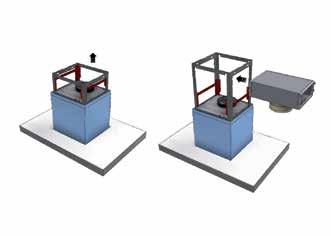
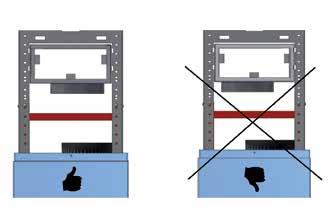
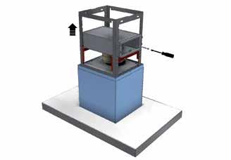
5 ALGEMENE INFORMATIE Algemeen Dit is de montage-instructie voor de Novy-dampkap met recirculatiekit. Gebruik deze montage instructie voor zowel de dampkap als voor de recirculatiekit. De gebruiksaanwijzing is een apart boekje dat bij de dampkap is meegeleverd. Lees deze instructies goed door voor de installatie en ingebruikname van de eilandschouwkap. Het is aan te bevelen om de installatie uitsluitend te laten uitvoeren door één of meerdere bevoegde personen. Neem de dampkap zorgvuldig uit de verpakking. De dampkap dient toegepast te worden boven een kookplaat en/of domino s en is uitsluitend bedoeld voor huishoudelijk gebruik. Belangrijk voordat u gaat monteren Op pagina 2 van deze montage-instructie vindt u de montagetekeningen. Voordat u gaat monteren, neem de volgende montagetips in acht: Voor het eenvoudiger monteren van de eilandschouwkap wordt aangeraden dit met minimaal 2 personen uit te voeren. Controleer aan de hand van de tekening op pagina 2 of alle montagematerialen meegeleverd zijn. Positioneer het stopcontact zodanig dat deze achter de schouwen van de schouw valt. Zorg dat het plafond over voldoende draagkracht beschikt. De beschermfolie op het rvs kunt u voor montage verwijderen van de eilandschouw of schouwen. Pas op voor beschadigingen van het rvs. INSTALLATIE Volg de montage tekeningen op pagina Neem de eilandschouw voorzichtig uit de verpakking. Schuif het bovenste schouwdeel uit het onderste schouwdeel en draai de schouw om, zodat het rooster aan de bovenzijde komt. Schuif hierna het bovenste schouwdeel voorzichtig weer terug in de onderste schouw. Neem de recirculatiebox uit de verpakking. Bevestig de meegeleverde afvoerbuis (906217) aan de aansluiting op de recirculatiebox met meegeleverde aluminiumtape (906292) of met een slangklem (niet meegeleverd). Zorg dat het kanaal goed vast zit aan de recirculatiebox, maar trek het kanaal nog niet verder uit. Schuif het ophangframe van de dampkap naar boven totdat de recirculatiebox ertussen geschoven kan worden. Het inschuiven gebeurt aan de zijde waar ook de bevestigingsgaten zitten. LET OP! Zorg bij het plaatsen van de recirculatiebox dat onderkant van X altijd boven het center van de aansluittuit H bevindt. Laat de recirculatiebox rusten in het ophangframe. Meet eerst de afstand vanaf het werkblad tot aan het plafond (A). Kies de hoogte tussen de onderzijde van de schouwkap en het werkblad (B) als volgt: - gas: minimaal 65 cm en maximaal 80 cm - inductie: minimaal 75 cm en maximaal 80 cm - overige kookplaten: minimaal 65 cm en maximaal 80 cm De afstand C is dan bepaald en wordt ingesteld d.m.v. het ophangframe van de eilandschouwkap. Het afstellen van de afstand C wordt bepaald door het schuiven van het ophangframe van de eilandschouwkap. Zodra de gekozen hoogte is ingesteld kan met 4 bouten (906133) het frame vast gezet worden. Draai de bouten goed vast. LET OP! Indien afstand C zich nabij de minimum hoogte van 679mm bevindt, wacht dan met het fixeren van het ophangframe totdat de afvoerbuis (die reeds bevestigd is aan de recirculatiebox) verbonden is met de uitlaat van het motorhuis (zodat in de volgende fase nog voldoende ruimte is om de afvoerbuis te fixeren). 8 9 Breng de recirculatiebox naar de voorziene uitsparing van het ophangframe. Buig de lipjes van de recirculatiebox om. De gaten in het ophangframe en van de recirculatiebox vallen mooi met elkaar overeen. Schroef de lipjes vast aan het ophangframe met de 4 schroeven (906151) 10 Monteer nu de afvoerbuis (die al gemonteerd is aan de recirculatiebox) aan de aansluittuit van de motor. LET OP! Indien het ophangframe nog niet gefixeerd was op de gewenste hoogte, dient dit nu gedaan te worden met de 4 schroeven (906151) De boormal bevind zich in de montage instructie van de dampkap. Plaats de boormal tegen het plafond in de juiste richting (zie aanduiding bediening) waar de eilandschouwkap gemonteerd zal worden. Markeer de bevestigingsgaten op het plafond. Boor de gaten met een 8mm boor. Plaats de 4 meegeleverde pluggen (906155). Neem het plafondframe en de schroeven (906143) en bevestig het plafondframe aan het plafond. BE 5
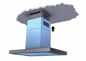
6 Pak met minimaal 2 personen de schouwkap op en til deze richting het plafondframe. Druk het ophangframe in het plafondframe zodat u KLIK hoort. Schroef de 4 bouten (906133) gedeeltelijk in de beide frames. Plaats de eilandschouwkap waterpas en draai dan de 4 bouten goed vast. Schuif het binnenste schouwdeel omhoog tot aan het plafond. Let op dat dit voorzichtig gedaan wordt i.v.m. beschadigen van de schouwkap of de schouwen. Bevestig deze met de 2 rvs schroeven (906035). Plaatsen van de Monoblock recirculatiefilter Open de onderplaat en neem het aluminium vetfilter van de schouwkap. Plaats de Monoblock recirculatiefilter ( ) in de voorziene opening. Plaats de vetfilter terug in de schouwkap en sluit de onderplaat. Programmering van het Monoblock recirculatiefilter Let op, doe deze programmering met de motor uitgeschakeld. Programmering: Druk de + en de gelijktijdig in gedurende 5 seconden tot de rode led 5x knippert. De volgende functies zijn dan in werking getreden: Nalooptijd is ingesteld op 30 minuten (i.p.v. de standaard 10 minuten) Reinigingsindicatie voor de Monoblock recirculatiefilter is ingesteld op 200 werkuren. Na 200 werkuren licht het rode led op. Dit is de indicatie om de Monoblock recirculatiefilter te reinigen (zie instructies hieronder, Herprogrammering: Druk de + en de gelijktijdig in gedurende 5 seconden. De rode led knippert 5x ter bevestiging. Indien de programmering niet wordt uitgevoerd, wordt de programmering automatisch ingesteld na 10x inschakelen van de schouwkap. Programmering deactiveren (de motor moet aanstaan): Druk de + en de gelijktijdig gedurende 5 seconden indrukken tot het 3e groene led 5x knippert. Reinigen Monoblock recirculatiefilter De Monoblock recirculatiefilter kan tot 12 maal toe geregenereerd worden. Dit gebeurt in de oven: Plaats het filter gedurende 1 uur in de oven op 120 C. Voorzie voldoende verluchting in de ruimte waar de oven staat, er kunnen geuren vrij komen. Bij het bakken van bepaalde vissoorten kan er geur vrij komen. Beste oplossing is meteen het filter regenereren in de oven. Wijzigingen en zet- of drukfouten voorbehouden, maart 2013 BE 6
7 INFORMATIONS GÉNÉRALES Généralités Il s agit de la notice de montage de la hotte Novy avec kit de recyclage. Utilisez cette notice de montage aussi bien pour la hotte que pour le kit de recyclage. Le mode d emploi consiste en un livret distinct fourni avec la hotte. Lisez attentivement ces instructions avant d installer et de mettre en service la hotte à cheminée îlot. Il est recommandé de confier l installation exclusivement à une ou plusieurs personnes compétentes. Retirez la hotte de son emballage avec précaution. La hotte doit être installée au-dessus d une table de cuisson et/ou de dominos. Elle est exclusivement à usage domestique. Important! Avant de commencer le montage Vous trouverez les dessins de montage en page 2 de cette notice de montage. Avant de commencer le montage, suivez les conseils de montage suivants : Pour faciliter le montage de la hotte à cheminée îlot, il est conseillé d y procéder avec 2 personnes. Vérifiez, en vous référant au dessin de la page 2, si tout le matériel a été livré. Positionnez la prise de courant de telle manière qu elle se trouve derrière les gaines de la cheminée. Assurez-vous que le plafond possède une capacité portante suffisante. Vous pouvez, avant le montage, enlever le film de protection sur l acier inoxydable de la cheminée îlot ou des gaines. Attention à ne pas endommager l acier inoxydable. INSTALLATION Suivez les dessins de montage en page Retirez la cheminée îlot de son emballage avec précaution. Dégagez la section de gaine supérieure de la section de gaine inférieure et retournez la gaine de manière à ce que la grille se trouve en haut. Puis réinsérez la section de gaine supérieure avec précaution dans la section de gaine inférieure. Retirez la boîte de recirculation de son emballage. Fixez le tuyau d évacuation fourni (906217) au raccord de boîte de recirculation à l aide du ruban adhésif aluminium fourni (906292) ou d un collier de serrage (non fourni). Assurez-vous que le conduit est correctement fixé à la boîte de recirculation, mais ne tirez pas davantage sur le conduit. Glissez le châssis de suspension de la hotte vers le haut jusqu à ce que la boîte de recirculation puisse se glisser entre eux. L insertion se fait du côté où se trouvent aussi les trous de montage. ATTENTION! Assurez-vous, lors de la mise en place de la boîte de recirculation, que le bas du X se trouve toujours au-dessus du centre du raccord H. Laisser reposer la boîte de recirculation dans le châssis de suspension. Mesurez d abord la distance entre le plan de travail et le plafond (A). Choisissez la hauteur entre le bas de la hotte à cheminée et le plan de travail (B) comme suit : - pour le gaz : 65 cm minimum et 80 cm maximum - pour induction : 75 cm minimum et 80 cm maximum - pour les autres tables de cuisson : 65 cm minimum et 80 cm maximum La distance C est alors déterminée et ajustée à l aide du châssis de suspension de la hotte à cheminée îlot. L ajustement de la distance C est déterminé en glissant le châssis de la hotte à cheminée îlot. Une fois que vous avez ajusté la hauteur sélectionnée, vous pouvez fixer le châssis à l aide de 4 boulons (906133). Serrez bien les boulons. ATTENTION! Si la distance C est proche de la hauteur minimale de 679 mm, ne fixez pas le châssis de suspension avant que le tuyau d évacuation (qui est déjà fixé à la boîte de recirculation) ne soit raccordé à l échappement du boîtier du moteur (de sorte que, dans l étape suivante, vous disposiez encore de suffisamment l espace pour fixer le tuyau d évacuation). 8 9 Amenez la boîte de recirculation à l ouverture prévue du châssis de suspension. Repliez les rebords de la boîte de recirculation. Les trous du châssis de suspension et de la boîte de recirculation se joignent parfaitement. Fixez les rebords contre le châssis de suspension à l aide des 4 vis (906151). 10 Maintenant, montez le tuyau d évacuation (qui est déjà monté sur la boîte de recirculation) contre le raccord du moteur. ATTENTION! Si le châssis de suspension n a pas été encore fixé à la hauteur souhaitée, vous devez le faire maintenant à l aide des quatre vis (906151) Le gabarit de perçage se trouve dans la notice de montage de la hotte. Placez le gabarit de perçage contre le plafond dans la bonne direction (voir l indication de la commande) où la hotte à cheminée îlot sera montée. Marquez les trous de fixation sur le plafond. Percez les trous avec une mèche de 8 mm. Placez les 4 chevilles fournies (906155). Prenez le châssis de plafond et les vis (906143) puis fixez ce châssis contre le plafond. FR 7
8 Saisissez la hotte à cheminée avec 2 personnes au moins et soulevez-la en direction du châssis du plafond. Poussez le châssis de suspension dans le châssis de plafond jusqu à ce que vous entendiez un CLIC. Vissez les 4 boulons (906133) partiellement dans les deux châssis. Placez la hotte à cheminée îlot de manière parfaitement horizontale puis serrez fermement les 4 boulons. Insérez l élément de gaine intérieur vers le haut jusqu au plafond. Veillez à ce que cela soit fait avec précaution en raison du risque d endommagement de la hotte à cheminée ou des gaines. Fixez-le avec les 2 vis en acier inoxydable (906035). Mise en place du filtre de recyclage Monoblock Ouvrez la plaque de fond et retirez le filtre à graisse en aluminium de la hotte à cheminée. Placez le filtre de recyclage Monoblock ( ) dans l ouverture prévue. Remettez le filtre à graisse en place et fermez la plaque inférieure. Programmation du filtre de recyclage Monoblock Attention : procédez à cette programmation pendant le moteur est à l arrêt. Programmation : Appuyez simultanément sur le + et le pendant 5 secondes jusqu à ce que la DEL clignote 5x. Les fonctions suivantes se trouvent alors activées : L arrêt différé est réglé à 30 minutes (au lieu des 10 minutes par défaut). Le voyant de nettoyage pour le filtre de recyclage Monoblock est réglé à 200 heures de service. La DEL rouge s allume après 200 heures de service. Il s agit de l indication signifiant que le filtre de recyclage Monoblock doit être nettoyé (voir les instructions ci-après). Reprogrammation : Appuyez simultanément sur le + et le pendant 5 secondes. La DEL rouge clignote 5x pour confirmation. Si la programmation n a pas été effectuée, elle se fera automatiquement après 10 mises sous tension de la hotte à cheminée. Désactivation de la programmation (le moteur doit être en marche) : Appuyez simultanément sur le + et le pendant 5 secondes jusqu à ce que la 3ème DEL verte clignote 5x. Nettoyage du filtre de recyclage Monoblock Le filtre de recyclage Monoblock peut être régénéré 12 fois. Cela s effectue dans le four : Placez le filtre dans le four pendant 1 heure à 120 C. Prévoyez une aération suffisante de la pièce où se trouve le four car des odeurs peuvent se dégager. La cuisson de certaines espèces de poisson peut dégager des odeurs. La meilleure solution est de régénérer juste après le filtre dans le four. Sous réserve de modifications et d erreurs de composition et d impression, mars 2013 FR 8
9 GENERAL INFORMATION General These are the mounting instructions for the Novy hood with recirculation kit. Use these mounting instructions for both the hood and the recirculation kit. The manual is a separate booklet that has been supplied with the hood. Carefully read these instructions before installing and commissioning the island chimney hood. It is recommended to have one or more qualified persons carry out the installation only. Carefully take the hood from the packaging. The hood is to be used above a cooking plate and/or domino and intended for household use only. Important before mounting Page 2 of these mounting instructions show the mounting drawings. Observe the following mounting tips before starting the mounting activities: For easier mounting of the island chimney hood, it is recommended to do this with at least 2 persons. Check if all mounting materials have been supplied using the drawing on page 2. Position the wall socket such, that it is behind the shafts of the chimney hood. Make sure that the ceiling has sufficient load bearing capacity. Remove the protective film from the stainless steel of the island chimney hood or shafts before mounting. Avoid damaging the stainless steel. INSTALLATION Proceed following the mounting drawings on page Carefully take the island hood out of the packaging. Slide the upper part of the shaft out of the lower part of the shaft and turn it around, so the grate is at the top. Then slide the upper part carefully back into the lower part. Remove the recirculation box from the packaging. Secure the supplied exhaust pipe (906217) onto the connection on the recirculation box using the supplied aluminium tape (906292) or using a hose clamp (not included). Ensure that the channel is securely attached to the recirculation box, but do not pull the channel out any further. Slide the hood mounting frame upwards until the recirculation box can be slid in between. Slide it in on the side where the mounting holes are also located. ATTENTION! When positioning the recirculation box, ensure that the underside X is always above the connecting spout H. Let the recirculation box rest in the mounting frame. First measure the distance between the work surface and the ceiling (A). Choose the height between the bottom of the chimney hood and the worktop (B) as follows: - gas: min. 65 cm and max. 80 cm - induction: min. 75 cm and max. 80 cm - other cooking plates: min. 65 cm and max. 80 cm Now the distance C has been determined and it is set with the help of the suspension frame of the island chimney hood. The distance C is set by sliding the suspension frame of the island chimney hood. As soon as the chosen height has been set, the frame can be fastened using 4 bolts (906133). Firmly tighten the bolts. ATTENTION! If distance C is close to the minimum height of 679 mm, leave the securing of the mounting frame until the outlet pipe (that is already attached to the recirculation box) is attached to the outlet of the motor housing (so that there is still sufficient clearance at the next phase for securing the outlet pipe). 8 9 Position the recirculation box by the recess in the mounting frame. Bend the lips of the recirculation box over. The holes in the mounting frame and those in the recirculation box align perfectly. Screw the lips to the mounting frame with the 4 screws (906151). 10 Now mount the outlet pipe (which is already attached to the recirculation box) onto the connection spout of the motor. ATTENTION! If the mounting frame has not yet been secured at the right height, this should be done now with the 4 screws (906151) The drilling jig is to be found in the mounting instructions of the hood. Position the drilling jig against the ceiling into the correct direction (see the indication for operation) at the place where the island chimney hood is to be mounted. Mark the fastening holes on the ceiling. Drill the holes with a 8 mm bit. Insert the 4 plugs (906155) supplied. Take the ceiling frame and the screws (906143) and fasten the ceiling frame onto the ceiling. EN 9
10 Pick up the chimney hood with at least 2 persons and lift it towards the ceiling frame. Press the suspension frame into the ceiling frame until you hear a click. Partly screw the 4 bolts (906133) into both frames. Level the island chimney hood and then firmly tighten the 4 bolts. Slide up the internal shaft part unto the ceiling. Do this carefully in order to prevent the chimney hood or the shafts from being damaged. Fasten them with the 2 stainless steel screws (906035). Install the Monoblock recirculation filter Open the bottom plate and remove the aluminium fat filter from the chimney hood. Place the Monoblock recirculation filter ( ) in the opening provided. Place the fat filter in the chimney hood again and close the bottom plate. Programme the Monoblock recirculation filter Attention! Do the programming with the motor switched off. Programme: Simultaneously press the + and the keys for 5 seconds until the red LED flashes 5 times. The following functions have now been enabled: The run-out time has been set to 30 minutes (instead of the default 10 minutes). The cleaning indicator for the Monoblock recirculation filter has been set to 200 operating hours. The red LED will light up after 200 operating hours. This indicates that the Monoblock recirculation filter needs cleaning (see the instructions below). Re-programming: Simultaneously press the + and the keys for 5 seconds. The red LED will flash 5 times for confirmation. If the programming is not carried out, the programming is automatically set after the chimney hood has been switched on 10 times. Inactivate the programming (the motor must have been switched on): Simultaneously press the + and the keys for 5 seconds until the 3rd green LED flashes 5 times. Clean the Monoblock recirculation filter The Monoblock recirculation filter can be regenerated up to 12 times. This is done in the oven: Place the filter in the oven for 1 hour at 120 C. Provide sufficient fresh air in the room where the oven has been placed, as smells can be released. Smells can be released when baking certain kinds of fish. In this case it is best to immediately regenerate the filter in the oven. Changes and misprints reserved, March 2013 EN 10
11 ALLGEMEINE INFORMATIONEN Allgemeine Informationen Dies ist die Montageanleitung für die Novy Dunstabzugshaube mit Umluftset. Verwenden Sie diese Montageanleitung sowohl für die Dunstabzugshaube als auch für das Umluftset. Die Gebrauchsanleitung ist ein separates Heft, das im Lieferumfang der Dunstabzugshaube enthalten ist. Lesen Sie sich diese Anleitung vor der Installation und Inbetriebnahme der Insel-Dunstabzugshaube sorgfältig durch. Es empfiehlt sich, die Installation ausschließlich durch eine oder mehrere autorisierte Person(en) durchführen zu lassen. Nehmen Sie die Dunstabzugshaube vorsichtig aus der Verpackung. Die Dunstabzugshaube ist für die Anbringung über Kochplatten und/oder Domino-Kochfeldern geeignet und ausschließlich für den Gebrauch im Haushalt vorgesehen. Wichtige vor der Montage zu beachtende Punkte Auf Seite 2 dieser Montageanleitung finden Sie die Montagezeichnungen. Bitte lesen Sie sich die folgenden Hinweise durch, bevor Sie mit der Montage beginnen: Die Insel-Dunstabzugshaube lässt sich einfacher montieren, wenn mindestens 2 Personen die Arbeiten durchführen. Kontrollieren Sie anhand der Zeichnung auf Seite 2, ob alle Befestigungsteile mitgeliefert wurden. Positionieren Sie die Steckdose so, dass sie hinter die Schächte der Dunstabzugshaube fällt. Stellen Sie sicher, dass die Tragfähigkeit der Decke ausreicht. Die Schutzfolie auf dem Edelstahl der Insel-Dunstabzugshaube oder Schächte können Sie vor der Montage entfernen. Achten Sie darauf, dass der Edelstahl nicht beschädigt wird. INSTALLATION Befolgen Sie die Montagezeichnungen auf Seite Nehmen Sie die Insel-Dunstabzugshaube vorsichtig aus der Verpackung. Schieben Sie das obere Schachtteil aus dem unteren Schachtteil heraus und drehen Sie den Schacht um, so dass sich das Gitter auf der Oberseite befindet. Schieben Sie anschließend das obere Schachtteil vorsichtig wieder zurück in das untere Schachtteil. Nehmen Sie die Umluftbox aus der Verpackung. Befestigen Sie das mitgelieferte Abluftrohr (906217) unter Verwendung des mitgelieferten Aluminium-Klebebands (906292) oder mit einer Schlauchklemme (nicht mitgeliefert) an dem Anschluss der Umluftbox. Achten Sie darauf, dass der Kanal sicher an der Umluftbox befestigt ist, aber ziehen Sie den Kanal noch nicht weiter heraus. Schieben Sie den Aufhängerahmen der Dunstabzugshaube nach oben, bis die Umluftbox dazwischen geschoben werden kann. Das Hineinschieben erfolgt auf der Seite, auf der sich auch die Befestigungslöcher befinden. ACHTUNG! Sorgen Sie beim Platzieren der Umluftbox dafür, dass sich die Unterkante von X immer über der Mitte der Anschlusstülle H befindet. Lassen Sie die Umluftbox im Aufhängerahmen aufliegen. Messen Sie zuerst den Abstand von der Arbeitsfläche zur Decke (A). Wählen Sie die Höhe zwischen der Unterseite der Dunstabzugshaube und der Arbeitsfläche (B) wie folgt: - Gas: mindestens 65 cm und höchstens 80 cm - Induktion: mindestens 75 cm und höchstens 80 cm - andere Kochplatten: mindestens 65 cm und höchstens 80 cm Der Abstand C ist jetzt festgelegt und wird mithilfe des Aufhängerahmens der Insel-Dunstabzugshaube eingestellt. Das Einstellen von Abstand C erfolgt, indem der Aufhängerahmen der Insel-Dunstabzugshaube verschoben wird. Sobald die gewählte Höhe eingestellt ist, kann der Rahmen mit 4 Schrauben (906133) befestigt werden. Drehen Sie die Schrauben sicher fest. ACHTUNG! Wenn Abstand C sich nahe der Mindesthöhe von 679 mm befindet, warten Sie mit dem Fixieren des Aufhängerahmens, bis das Abluftrohr (das bereits an der Umluftbox befestigt ist) mit dem Auslass des Motorgehäuses verbunden ist (so dass beim nächsten Schritt der Platz noch ausreicht, um das Abluftrohr zu fixieren). 8 9 Bringen Sie die Umluftbox zu der vorgesehenen Aussparung des Aufhängerahmens. Biegen Sie die Laschen der Umluftbox um. Die Löcher im Aufhängerahmen und von der Umluftbox decken sich sehr gut. Schrauben Sie die Laschen mit 4 Schrauben (906151) am Aufhängerahmen fest. 10 Montieren Sie jetzt das Abluftrohr (das bereits an der Umluftbox montiert ist) an der Anschlusstülle des Motors. ACHTUNG! Wenn der Aufhängerahmen noch nicht auf der gewünschten Höhe fixiert war, muss dies jetzt mit den 4 Schrauben (906151) erfolgen Die Bohrschablone befindet sich in der Montageanleitung für die Dunstabzugshaube. Halten Sie die Bohrschablone in der richtigen Richtung (siehe Angabe Bedienung) dort an die Decke, wo die Insel-Dunstabzugshaube montiert werden soll. Zeichnen Sie die Befestigungslöcher auf der Decke an. Bohren Sie die Löcher mit einem 8-mm-Bohrer. DE 11
12 Stecken Sie die 4 mitgelieferten Dübel (906155) in die Löcher. Nehmen Sie den Deckenrahmen und die Schrauben (906143) und befestigen Sie den Deckenrahmen an der Decke. Greifen Sie mindestens zu zweit die Dunstabzugshaube an und heben Sie sie Richtung Deckenrahmen. Drücken Sie den Aufhängerahmen in den Deckenrahmen, bis Sie ein Einrastgeräusch hören. Schrauben Sie die 4 Schrauben (906133) teilweise in die beiden Rahmen. Positionieren Sie die Insel-Dunstabzugshaube horizontal und drehen Sie anschließend die 4 Schrauben sicher fest. Schieben Sie den inneren Schachtteil bis zur Decke nach oben. Gehen Sie dabei vorsichtig vor, damit die Wandhaube oder die Schächte nicht beschädigt werden. Befestigen Sie ihn mit den 2 Edelstahlschrauben (906035). Positionieren des Monoblock-Umluftfilters Öffnen Sie die Unterseite und nehmen Sie den Fettfilter aus Aluminium aus der Wandhaube heraus. Positionieren Sie den Monoblock-Umluftfilter ( ) in der vorgesehenen Öffnung. Setzen Sie den Fettfilter zurück in die Dunstabzugshaube und schließen Sie die Unterplatte. Programmieren des Monoblock-Umluftfilters Achtung - Führen Sie diese Programmierung bei ausgeschaltetem Motor durch. Programmierung: Drücken Sie gleichzeitig 5 Sekunden lang + und, bis die rote LED 5x blinkt. Die folgenden Funktionen sind jetzt aktiv: Die Nachlaufzeit ist auf 30 Minuten eingestellt (anstelle der standardmäßigen 10 Minuten). Die Reinigungsanzeige für den Monoblock-Umluftfilter ist auf 200 Betriebsstunden eingestellt. Nach 200 Betriebsstunden leuchtet die rote LED auf und weist dadurch darauf hin, dass der Monoblock-Umluftfilter gereinigt werden muss (wie weiter unten beschrieben). Umprogrammierung: Drücken Sie gleichzeitig 5 Sekunden lang + und. Die rote LED blinkt zur Bestätigung 5x. Wenn die Programmierung nicht durchgeführt wird, erfolgt sie automatisch nach 10x Einschalten der Dunstabzugshaube. Programmierung deaktivieren (der Motor muss eingeschaltet sein): Drücken Sie gleichzeitig 5 Sekunden lang + und, bis die 3. grüne LED 5x blinkt. Reinigen des Monoblock-Umluftfilters Der Monoblock-Umluftfilter kann bis zu 12 Mal regeneriert werden. Dies geschieht im Ofen: Legen Sie den Filter 1 Stunde lang in den auf 120 C aufgeheizten Ofen. Sorgen Sie für eine ausreichende Belüftung des Raums, in dem sich der Ofen befindet, da eventuell Gerüche entstehen. Beim Backen von bestimmten Fischsorten können Gerüche entstehen. In diesem Fall besteht die beste Lösung darin, den Filter umgehend im Ofen zu regenerieren. Änderungen und Satz- oder Druckfehler vorbehalten, März 2013 DE 12
13 ALGEMENE INFORMATIE Algemeen Dit is de montage-instructie voor de Novy-afzuigkap met recirculatiekit. Gebruik deze montage instructie voor zowel de afzuigkap als voor de recirculatiekit. De gebruiksaanwijzing is een apart boekje dat bij de afzuigkap is meegeleverd. Lees deze instructies goed door voor de installatie en ingebruikname van de eilandschouwkap. Het is aan te bevelen om de installatie uitsluitend te laten uitvoeren door één of meerdere bevoegde personen. Neem de afzuigkap zorgvuldig uit de verpakking. De afzuigkap dient toegepast te worden boven een kookplaat en/of domino s en is uitsluitend bedoeld voor huishoudelijk gebruik. Belangrijk voordat u gaat monteren Op pagina 2 van deze montage-instructie vindt u de montagetekeningen. Voordat u gaat monteren, neem de volgende montagetips in acht: Voor het eenvoudiger monteren van de eilandschouwkap wordt aangeraden dit met minimaal 2 personen uit te voeren. Controleer aan de hand van de tekening op pagina 2 of alle montagematerialen meegeleverd zijn. Positioneer het stopcontact zodanig dat deze achter de schachten van de schouw valt. Zorg dat het plafond over voldoende draagkracht beschikt. De beschermfolie op het rvs kunt u voor montage verwijderen van de eilandschouw of schachten. Pas op voor beschadigingen van het rvs. INSTALLATIE Volg de montage tekeningen op pagina Neem de eilandschouw voorzichtig uit de verpakking. Schuif het bovenste schachtdeel uit het onderste schachtdeel en draai de schacht om, zodat het rooster aan de bovenzijde komt. Schuif hierna het bovenste schachtdeel voorzichtig weer terug in de onderste schacht. Neem de recirculatiebox uit de verpakking. Bevestig de meegeleverde afvoerbuis (906217) aan de aansluiting op de recirculatiebox met meegeleverde aluminiumtape (906292) of met een slangklem (niet meegeleverd). Zorg dat het kanaal goed vast zit aan de recirculatiebox, maar trek het kanaal nog niet verder uit. Schuif het ophangframe van de afzuigkap naar boven totdat de recirculatiebox ertussen geschoven kan worden. Het inschuiven gebeurt aan de zijde waar ook de bevestigingsgaten zitten. LET OP! Zorg bij het plaatsen van de recirculatiebox dat onderkant van X altijd boven het center van de aansluittuit H bevindt. Laat de recirculatiebox rusten in het ophangframe. Meet eerst de afstand vanaf het werkblad tot aan het plafond (A). Kies de hoogte tussen de onderzijde van de schouwkap en het werkblad (B) als volgt: - gas: minimaal 65 cm en maximaal 80 cm - inductie: minimaal 75 cm en maximaal 80 cm - overige kookplaten: minimaal 65 cm en maximaal 80 cm De afstand C is dan bepaald en wordt ingesteld d.m.v. het ophangframe van de eilandschouwkap. Het afstellen van de afstand C wordt bepaald door het schuiven van het ophangframe van de eilandschouwkap. Zodra de gekozen hoogte is ingesteld kan met 4 bouten (906133) het frame vast gezet worden. Draai de bouten goed vast. LET OP! Indien afstand C zich nabij de minimum hoogte van 679mm bevindt, wacht dan met het fixeren van het ophangframe totdat de afvoerbuis (die reeds bevestigd is aan de recirculatiebox) verbonden is met de uitlaat van het motorhuis (zodat in de volgende fase nog voldoende ruimte is om de afvoerbuis te fixeren). Breng de recirculatiebox naar de voorziene uitsparing van het ophangframe. Buig de lipjes van de recirculatiebox om. De gaten in het ophangframe en van de recirculatiebox vallen mooi met elkaar overeen. Schroef de lipjes vast aan het ophangframe met de 4 schroeven (906151) 10 Monteer nu de afvoerbuis (die al gemonteerd is aan de recirculatiebox) aan de aansluittuit van de motor. LET OP! Indien het ophangframe nog niet gefixeerd was op de gewenste hoogte, dient dit nu gedaan te worden met de 4 schroeven (906151). NL 13
 waar de eilandschouwkap gemonteerd zal worden. Markeer de bevestigingsgaten op het plafond.")

.")
14 11 12 De boormal bevind zich in de montage instructie van de afzuigkap. Plaats de boormal tegen het plafond in de juiste richting (zie aanduiding bediening) waar de eilandschouwkap gemonteerd zal worden. Markeer de bevestigingsgaten op het plafond. Boor de gaten met een 8mm boor. Plaats de 4 meegeleverde pluggen (906155). Neem het plafondframe en de schroeven (906143) en bevestig het plafondframe aan het plafond.pak met minimaal 2 personen de schouwkap op en til deze richting het plafondframe. Druk het ophangframe in het plafondframe zodat u KLIK hoort. Schroef de 4 bouten (906133) gedeeltelijk in de beide frames. Plaats de eilandschouwkap waterpas en draai dan de 4 bouten goed vast. Schuif het binnenste schouwdeel omhoog tot aan het plafond. Let op dat dit voorzichtig gedaan wordt i.v.m. beschadigen van de schouwkap of de schouwen. Bevestig deze met de 2 rvs schroeven (906035) Pak met minimaal 2 personen de schouwkap op en til deze richting het plafondframe. Druk het ophangframe in het plafondframe zodat u KLIK hoort. Schroef de 4 bouten (906133) gedeeltelijk in de beide frames. Plaats de eilandschouwkap waterpas en draai dan de 4 bouten goed vast. Schuif het binnenste schachtdeel omhoog tot aan het plafond. Let op dat dit voorzichtig gedaan wordt i.v.m. beschadigen van de schouwkap of de schachten. Bevestig deze met de 2 rvs schroeven (906035). Plaatsen van de Monoblock recirculatiefilter Open de onderplaat en neem het aluminium vetfilter van de schouwkap. Plaats de Monoblock recirculatiefilter ( ) in de voorziene opening. Plaats de vetfilter terug in de schouwkap en sluit de onderplaat. Programmering van het Monoblock recirculatiefilter Let op, doe deze programmering met de motor uitgeschakeld. Programmering: Druk de + en de gelijktijdig in gedurende 5 seconden tot het rode led 5x knippert. De volgende functies zijn dan in werking getreden: Nalooptijd is ingesteld op 30 minuten (i.p.v. de standaard 10 minuten) Reinigingsindicatie voor het Monoblock recirculatiefilter is ingesteld op 200 werkuren. Na 200 werkuren licht het rode led op. Dit is de indicatie om het Monoblock recirculatiefilter te reinigen (zie instructies hieronder, Herprogrammering: Druk de + en de gelijktijdig in gedurende 5 seconden. Het rode led knippert 5x ter bevestiging. Indien de programmering niet wordt uitgevoerd, wordt de programmering automatisch ingesteld na 10x inschakelen van de schouwkap. Programmering deactiveren (de motor moet aanstaan): Druk de + en de gelijktijdig gedurende 5 seconden indrukken tot het 3e groene led 5x knippert. Reinigen Monoblock recirculatiefilter Het Monoblock recirculatiefilter kan tot 12 maal toe geregenereerd worden. Dit gebeurt in de oven: Plaats het filter gedurende 1 uur in de oven op 120 C. Voorzie voldoende verluchting in de ruimte waar de oven staat, er kunnen geuren vrij komen. Bij het bakken van bepaalde vissoorten kan er geur vrij komen. Beste oplossing is meteen het filter regenereren in de oven. Wijzigingen en zet- of drukfouten voorbehouden, maart 2013 NL 14
15
16 NOVY nv behoudt zich het recht voor te allen tijde en zonder voorbehoud de constructie en de prijzen van haar producten te wijzigen. NOVY SA se réserve le droit de modifier en tout temps et sans préavis la construction et les prix de ses produits. Die NOVY AG behält sich das Recht vor, zu jeder Zeit und ohne Vorbehalt die Konstruktion und die Preise ihrer Produkte zu ändern. NOVY nv Noordlaan 6 B KUURNE Tel. 056/ Fax 056/ novy@novy.be France: Tél: Deutschland und Österreich: Tel: +49 (0) M A
NL - België Installatievoorschriften p. 3 Nederland. FR - Belgique Instructions d installation p. 5 France
 NL - België Installatievoorschriften p. 3 Nederland FR - Belgique Instructions d installation p. 5 France EN Operating and installation Instructions p. 11 DE - Belgien Montageanleitung p. 13 Deutschland
NL - België Installatievoorschriften p. 3 Nederland. FR - Belgique Instructions d installation p. 5 France
 NL - België Installatievoorschriften p. 3 Nederland FR - Belgique Instructions d installation p. 5 France DE - Belgien Montageanleitung p. 11 Deutschland 7241/15-7251/15-7490/15 7246/15-7256/15-7495/15
NL - België Installatievoorschriften p. 3 Nederland Installatievoorschriften. FR - France Instructions d installation p.
 NL - België Installatievoorschriften p. 3 Nederland Installatievoorschriften FR - France Instructions d installation p. 4 Belgique Suisse DE - Deutschland Montageanleitung p. 5 Belgien Österreich Schweiz
NL - België Installatievoorschriften p. 3 Nederland. FR - Belgique Instructions d installation p. 4 France
 NL - België Installatievoorschriften p. 3 Nederland FR - Belgique Instructions d installation p. 4 France DE - Belgien Montageanleitung p. 5 Deutschland 680400 1 Lees aandachtig deze instructies voor de
NL - België Installatievoorschriften p. 3 Nederland. FR - Belgique Instructions d installation p. 6 France
 NL - België Installatievoorschriften p. 3 Nederland FR - Belgique Instructions d installation p. 6 France DE - Belgien Montageanleitung p. 8 Deutschland Österreich Schweiz 7211/15-7221/15-7470/15 7216/15-7226/15-7475/15
NL - België Installatievoorschriften p. 3 Nederland. FR - France Instructions d installation p. 5 Belgique Suisse
 NL - België Installatievoorschriften p. 3 Nederland FR - France Instructions d installation p. 5 Belgique Suisse DE - Deutschland Montageanleitung p. 7 Belgien Österreich Schweiz 7800/16-7805/16 5 6 6
NL Installatievoorschriften p. 3. FR Instructions d installation p. 5. DE Montageanleitung p. 6. EN Operating and installation Instructions p.
 NL Installatievoorschriften p. 3 FR Instructions d installation p. 5 DE Montageanleitung p. 6 EN Operating and installation Instructions p. 8 7550 1 2 3 4 5 6 7 ALGEMENE INFORMATIE Algemeen Dit is de montage-instructie
NL - België Installatievoorschriften p. 3. FR - Belgique Instructions d installation p. 5 France
 NL - België Installatievoorschriften p. 3 FR - Belgique Instructions d installation p. 5 France DE - Belgien Montageanleitung p. 7 Deutschland Österreich Schweiz NL - Nederland Installatievoorschriften
NL - België Installatievoorschriften p. 4 Nederland. FR - Belgique Instructions d installation p. 6 France
 NL - België Installatievoorschriften p. 4 Nederland FR - Belgique Instructions d installation p. 6 France DE - Belgien Montageanleitung p. 8 Deutschland 7810400 7810.400-C Montage NL-FR-DE.indd 1 23/06/14
GB - Installation manual Mercedes Benz C-Class A205 convertible wind deflector (from 2015).
.") GB - Installation manual Mercedes Benz C-Class A205 convertible wind deflector (from 2015). DE Montage Anleitung Mercedes Benz C-Klasse Cabrio Windschott (ab 2015). NL Montage handleiding Mercedes Benz
GB - Installation manual Mercedes Benz C-Class A205 convertible wind deflector (from 2015). DE Montage Anleitung Mercedes Benz C-Klasse Cabrio Windschott (ab 2015). NL Montage handleiding Mercedes Benz
NL - België Installatievoorschriften p. 3. FR - Belgique Instructions d installation p. 5 France. EN Operating and installation Instructions p.
 NL - België Installatievoorschriften p. 3 FR - Belgique Instructions d installation p. 5 France EN Operating and installation Instructions p. 7 DE - Belgien Montageanleitung p. 9 Deutschland Österreich
Montage-instructie Instruction manual Montage-Anleitung. Doorkeeper
 Montage-instructie Instruction manual Montage-Anleitung Doorkeeper NEDERLANDS Montage INTERSTEEL Doorkeeper 1. De geadviseerde montagehoogte is ca. 145 cm. Teken deze af op uw kozijn. 2. Gebruik de bijgeleverde
NL - België Installatievoorschriften p. 3. FR - Belgique Instructions d installation p. 4 France. DE - Belgien Montageanleitung p.
 NL - België Installatievoorschriften p. 3 FR - Belgique Instructions d installation p. France DE - Belgien Montageanleitung p. Deutschland NL - Nederland Installatievoorschriften p. 6 820.00/1 80.00 3
Plaatsingsvoorschriften Govawall Instructions de montage Govawall Verlegeanleitung Govawall Installation instructions Govawall
 V s u stainable p r i va c y NL F D UK Plaatsingsvoorschriften Govawall Instructions de montage Govawall Verlegeanleitung Govawall Installation instructions Govawall - + 502 40 502 6 x Ø 6 mm 2590 502
NL - België Installatievoorschriften p. 3 Nederland. FR - Belgique Instructions d installation p. 5 France
 NL - België Installatievoorschriften p. 3 Nederland FR - Belgique Instructions d installation p. 5 France EN Operating and installation Instructions p. 11 DE - Belgien Montageanleitung p. 13 Deutschland
1/8 ATLAS Atlas cabinet cabinet 1 7
 TLS cabinet / / / 0 D E F G H / L x Lx x L / x x D E Dx Ex / x x x x x x Fx x Hx Gx Fx Fx Fx Fx G H G H H G 0 0 0 0 0 / L / 0 NL: Deze kast bevat twee gaten aan de achterkant om aan de wand te kunnen bevestigen.
NL Installatievoorschriften p. 3. FR Instructions d installation p. 5
 NL Installatievoorschriften p. 3 FR Instructions d installation p. 5 6202 1 5 2 6 3 7 4 8 ALGEMENE INFORMATIE Algemeen Dit is de montage-instructie voor de op de voorzijde aangegeven Novy-afzuigkap. De
Installatievoorschriften Kit met monoblock koolfilter Instructions d installation Kit avec filtre à charbon monoblock Montageanleitung Kit mit
 7450400 Installatievoorschriften Kit met monoblock koolfilter Instructions d installation Kit avec filtre à charbon monoblock Montageanleitung Kit mit monoblock Aktivkohlefilter 1 x 7250052 4 x 906148
Rhythm of Light. Susanne de Graef, Montagehandleiding / Instruction manual
 Rhythm of Light Susanne de Graef, 2016 Montagehandleiding / Instruction manual GELEVERD MATERIAAL / SUPPLIED MATERIAL B. C. D. A. E. F. A. B. C. D. E. F. armatuur / fixture fitting lange staalkabels (3)
OUTDOOR HD BULLET IP CAMERA PRODUCT MANUAL
 OUTDOOR HD BULLET IP CAMERA PRODUCT MANUAL GB - NL GB PARTS & FUNCTIONS 1. 7. ---- 3. ---- 4. ---------- 6. 5. 2. ---- 1. Outdoor IP camera unit 2. Antenna 3. Mounting bracket 4. Network connection 5.
NL - België Installatievoorschriften p. 3. FR - Belgique Instructions d installation p. 5 France. EN Operating and installation Instructions p.
 NL - België Installatievoorschriften p. 3 FR - Belgique Instructions d installation p. 5 France EN Operating and installation Instructions p. 7 DE - Belgien Montageanleitung p. 13 Deutschland Österreich
Bullerjan B 4 Stahl, Keramik und Keramik+
 Bullerjan B 4 Stahl, Keramik und Keramik+ Anleitung zur Montage der Tür für die Holzbox Instruction for the mounting of the door for wood storage box Instructions pour le montage de la porte de la boîte
Installatievoorschriften Motor op afstand buiten Instructions d installation Moteur dissocié extérieur Montageanleitung Externes Motor Außenwand
 44999/1 Installatievoorschriften Motor op afstand buiten Instructions d installation Moteur dissocié extérieur Montageanleitung Externes Motor Außenwand 4 x 90606 x 90604 1 x 906292 1 x 71011 1 x 906287
COLD/FREEZER ROOM. Gebruikershandleiding. Gebrauchsanweisung Owners manual Le mode d emploi
 COLD/FREEZER ROOM Gebruikershandleiding Gebrauchsanweisung Owners manual Le mode d emploi 1 CONTENT 1 Assembly of the cold rooms Kühlraum montage Assemblage des chambres froid Montage van de koelcel...
OUTDOOR HD DOME IP CAMERA PRODUCT MANUAL GB - NL
 OUTDOOR HD DOME IP CAMERA PRODUCT MANUAL GB - NL GB PARTS & FUNCTIONS 2. ---- 1. ---- 3. ---- 7. ---------- 5. 4. 6. 1. Outdoor IP camera unit 2. Antenna 3. Mounting bracket 4. Network connection 5. Power
LICHTKOEPEL INBRAAKWEREND
 LICHTKOEPEL INBRAAKWEREN Installatieadvies Installation advice Installationshinweise Lichtkoepel Inbraakwerend omelight Burglary resistant Lichtkuppel Einbruchhemmend NL Product samenstelling 1 Lichtkoepel
CONTENU DU CARTON CGI DÉTAIL DU SACHET VISSERIE
 F Page Les informations contenues dans ce manuel vont vous permettre de procéder au montage et à l utilisation du produit, en toute sécurité pour vous et votre entourage. Vous devez prendre connaissance
FSW-VW-2X2 FSW-VW. Handleiding / Manual
 FSW-VW-2X2 FSW-VW Handleiding / Manual Rev. 1.0 17-03-2014 I Pakketinhoud / Content Accessoires Benodigde gereedschappen / Required Tools Montage / Assembling Onderhoud / Maintenance Veel Gestelde Vragen
2000 Volkswagen Passat GLS
 REAR DOOR WINDOW Rear door window, assembly overview Fig. 304: Exploded View Of Rear Door Window 1 - Door Removing and installing: --> Rear door, removing and installing 2 - Spring nut Qty 2 3 - Screw
Bestellen van reserve onderdelen: Ordening for spare parts: Ersatzteit bestellung: Commander piece de rechange:
 100020 2 schommelzitje swingseat Schaukelsitz siege 2 grote hoeksteun cornerconnector Eckverbinder assemblages d angle 1 kleine hoeksteun cornerconnector small Eckverbinder klein assemblages d angle petit
Limpid Light. design Esther Jongsma & Sam van Gurp, Montagehandleiding / Assembly Instructions
 Limpid Light design Esther Jongsma & Sam van Gurp, 05 Montagehandleiding / Assembly Instructions GELEVERD MATERIAAL / SUPPLIED MATERIAL A. A. B. B. C. D. E. F. G. G. H. I. J. K. / / ophanging / suspension:
Anleitung SWS Wireless Display
 Anleitung SWS Wireless Display E A B C D F G H I J K L M N O A B C D E F G H Massage ein Massage aus Abnahme Massage Intensität Zunahme Massage Intensität Taschenlampe Display Taschenlampe ein/aus Bodenbeleuchtung
OPEL OMEGA SEDAN Model /1999- OPEL OMEGA STATION Model /1999-
 OP-06-BB 099I Einbauanleitung Elektrosatz nhängervorrichtung mit -N Steckdose lt. DIN/ISO Norm 74 Instructions de montage du faisceau électrique pour crochet d attelage conforme á la norme DIN/ISO 74 prise
Flat line NL - Installatievoorschriften p. 4. FR - Instructions d installation p. 7. DE - Montageanleitung p.
 NL - Installatievoorschriften p. 4 FR - Instructions d installation p. 7 DE - Montageanleitung p. 14 EN - Operating and installation Instructions p. 16 Flat line 7600-7602 - 7605 7610-7615 7600_110061_MA1
Flybye. Ernst Koning, Montagehandleiding / Instruction manual
 Flybye Ernst Koning, 2018 Montagehandleiding / Instruction manual GELEVERD MATERIAAL / MATERIALS SUPPLIED A. B. C. D. E. F. G. A. B. C. D. E. F. G. H. H. lichtbuis / lighting tube plafondkap / ceiling
GEBRUIKSAANWIJZING USER INSTRUCTIONS GEBRAUCHSANWEISUNG MODE D EMPLOI
 GEBRUIKSAANWIJZING USER INSTRUCTIONS GEBRAUCHSANWEISUNG MODE D EMPLOI Alvorens de apparatuur in gebruik te nemen dient u deze gebruiksaanwijzing aandachtig te lezen: You should read these user instructions
NL Installatievoorschriften p. 4. FR Instructions d installation p. 6. DE Montageanleitung p. 8. EN Operating and installation instructions p.
 NL Installatievoorschriften p. 4 FR Instructions d installation p. 6 DE Montageanleitung p. 8 EN Operating and installation instructions p. 11 7830/1-7831/1 7840/1-7841/1 1 3 2 4 5 6 7 8 9 10 ALGEMENE
Model : SE 90 DFT BLACK Type : YK96P5123E22C0S SERIAL NO:
 230V 50Hz 3000W Model : SE 90 DFT BLACK Type : YK96P5123E22C0S SERIAL NO: 51000001444443916 SN: 00610518000462880001 SKU Code: BE444444696 G20 20mbar *NL: II2L3B/P + II2EK3B/P G25/25.3 25mbar BE: II2E+3+
Monteringsvejledning (DK) Montering af lændestøtte på Wombat. Mounting instruction (GB) Mounting the lumbar support
 Montering af lændestøtte på Wombat. Mounting instruction (GB) Mounting the lumbar support") Monteringsvejledning (K) Montering af lændestøtte på Wombat Mounting instruction (G) Mounting the lumbar support Montageanleitung () Montage der Lendenunterstützung Montage instructies (NL) evestiging
Monteringsvejledning (K) Montering af lændestøtte på Wombat Mounting instruction (G) Mounting the lumbar support Montageanleitung () Montage der Lendenunterstützung Montage instructies (NL) evestiging
NL - België Installatievoorschriften p. 3 Nederland. FR - Belgique Instructions d installation p. 4 France
 NL - België Installatievoorschriften p. 3 Nederland FR - Belgique Instructions d installation p. 4 France DE - Belgien Montageanleitung p. 5 Deutschland Österreich Schweiz 810/15-811/15 820/15-821/15 810/811
DE Wippadapter für Jung-Serien Seite 2 EN Rocker adapter for Jung series Page 3. Adaptateur à bascule pour les séries Jung. Page 4
 DE Wippadapter für Jung-Serien Seite 2 EN Rocker adapter for Jung series Page 3 FR Adaptateur à bascule pour les séries Jung Page 4 NL Schakelaaradapter voor Jung-series Pagina 5 DE Funktion Die Wippadapter
7456/11-7465/11-7466/11-7245/12-7246/12-7255/12-7256/12-7495/11
 NL - België Installatievoorschriften p. 3 FR - Belgique Instructions d installation p. 6 France DE - Belgien Montageanleitung p. 7 Deutschland NL - Nederland Installatievoorschriften p. 8 7450/11-7451/11-7460/11-7461/11-7240/12-7241/12-7250/12-7251/12-7490/11-7455/11
MONTAGEHANDLEIDING/NOTICE D INSTALLATION
 MONTAGEHANDLEIDING/NOTICE D INSTALLATION Ribbon douchecabine / cabine de douche (ref. 223216) Barna douchecabine / cabine de douche (ref. 223217)! Voor uw gemak zijn de wanden en tub van deze douchecabine
Lamellenpergola. Vor Montage und Benutzung unbedingt sorgfältig lesen und für spätere Zwecke aufbewahren.
 Vor Montage und Benutzung unbedingt sorgfältig lesen und für spätere Zwecke aufbewahren. Read these instructions carefully before use and assembly and keep for future reference! Lees deze instructies zorgvuldig
Bestel Nr.: OP-016-BB
 Einbauanleitung Elektrosatz nhängervorrichtung mit -N Steckdose lt. DIN/ISO Norm 74 Instructions de montage du faisceau électrique pour crochet d attelage conforme á la norme DIN/ISO 74 prise -N Fitting
NL - België Installatievoorschriften p. 5. FR - Belgique Instructions d installation p. 7 France. EN Operating and installation Instructions p.
 NL - België Installatievoorschriften p. 5 FR - Belgique Instructions d installation p. 7 France EN Operating and installation Instructions p. 9 DE - Belgien Montageanleitung p. 11 Deutschland Österreich
NL - België Installatievoorschriften p. 3 Nederland. FR - Belgique Instructions d installation p. 8 France
 NL - België Installatievoorschriften p. 3 Nederland FR - Belgique Instructions d installation p. 8 France DE - Belgien Montageanleitung p. 14 Deutschland Österreich Schweiz EN Operating and installation
2006 Volkswagen Jetta TDI
 Door handle and door lock, assembly overview The illustration shows the left side. The right side is derived accordingly from this. Fig. 99: Door Handle And Door Lock, Assembly Overview 1 - Cable For disengaging
Mitsubishi L200 4WD
 Trekhaken Attelages Anhängevorrichtungen Tow bars GDW EEC APPROVAL N : e4*94/20*0433*00 D/ : 13,60 KN S/ : 120 kg Max. : 2700 kg : 0000 kg Montagehandleiding 1) Bumper achteraan definitief verwijderen.
Aufbauanleitung Verbundsicherheitsglas 10mm Assembly instructions / Instructions de montage / Montagehandleiding
 Aufbauanleitung Verbundsicherheitsglas 10mm Assembly instructions / Instructions de montage / Montagehandleiding Dacheindeckung / Roofing / Toiture / Dakbedekking 6 Versenken Sie die Schraube mindestens
INSTALLATIONS- UND BEDIENUNGSANLEITUNG GREE KLIMAANLAGEN KONSOLEGERÄT:
 INSTALLATIONS- UND BEDIENUNGSANLEITUNG GREE KLIMAANLAGEN KONSOLEGERÄT: GEH 09 AA - K3DNA1B (R 410 A) GEH 12 AA - K3DNA1B (R 410 A) GEH 18 AA - K3DNA1B (R 410 A) Lesen Sie diese Anleitung bitte ausführlich
INSTALATIEGIDS VIDEOWALL
 INSTALATIEGIDS VIDEO 1. Bereken de hoogte van de rails door te meten hoeveel lager het onderste scherm zal uitkomen. Je kan dit meten aan de achterkant van de display, waar de beugels op gemonteerd zijn.
GEVELPANELEN PANNEAUX DE FACADE
 Handleiding Manuel GEVELPANELEN PANNEAUX DE FACADE update van 11/09/2015 www.scalaplastics.com Gereedschappen en bevestigingsmiddelen: Hamer, meetlint, metaalzaag met een cirkelzaagblad met fijne tanden,
heatwave large Montagehandleiding - Instructions de montage Montageanleitung - Mounting instructions
 1 heatwave large Montagehandleiding - Instructions de montage Montageanleitung - Mounting instructions *Standaard positie / Standard position / Position standard 1040 mm / 40.95 in 56 kg / 124 lb 2086
MONTAGE INSTRUCTIE ASSEMBLY INSTRUCTION
 MONTAGE INSTRUCTIE ASSEMBLY INSTRUCTION - 1. Waterpas stellen. De groef aan de zijkant van de beschermdeksel moet gelijk staan met de deellijn van het inbouw box. 2. Zet de inbouw box vast in de muur.
Hollywoodschaukel / Hollywood - Swing / Hollywood - Schommelbank
 Vor Montage und Benutzung unbedingt sorgfältig lesen und für spätere Zwecke aufbewahren. Read these instructions carefully before use and assembly and keep for future reference! Lees deze instructies zorgvuldig
NL - België Installatievoorschriften p. 3. FR - Belgique Instructions d installation p. 4 France. DE - Belgien Montageanleitung p.
 NL - België Installatievoorschriften p. FR - Belgique Instructions d installation p. France DE - Belgien Montageanleitung p. Deutschland NL - Nederland Installatievoorschriften p. 6 00/ - 0/ 6 x 060 x
Handleiding Wallwash Downlight
 Handleiding Wallwash Downlight 3000K WARM 3900 4000K COOL 4200 5 JAAR 43 WATT 50.000 UUR CRI >82 >10.000 x < 0,01 90-60 GRADEN PF 0.95 VAC 230 HANDLEIDING IL-DWW43K3 / IL-DWW43K4 Installatie INPUT: 100-240V
DRAAIDEUR 80/90 PIVOT DOOR
 HANDLEIDING MANUAL DRAAIDEUR 80/90 PIVOT DOOR 800/900 Montagehandleiding Reflex draaideur 80/90 met zijpaneel 80/90 Verstelbaarheid 611801: (770-810) x (770-810) x 1850 mm Verstelbaarheid 611802: (870-910)
NL - België Installatievoorschriften p. 3 Nederland. FR - Belgique Instructions d installation p. 5 France
 NL - België Installatievoorschriften p. 3 Nederland FR - Belgique Instructions d installation p. 5 France DE - Belgien Montageanleitung p. 11 Deutschland 7241/15-7251/15-7490/15 7246/15-7256/15-7495/15
SAXO SL SCENIC SL METRO XT2 METRO XT3
 INSTALLATIEVOORSCHRIFT NL/BE INSTRUCTIONS FOR INSTALLATION GB/IE INSTALLATIONSVORSCHRIFT DE/AT/BE/LU/CH INSTRUCTIONS D INSTALLATION FR/BE/LU/CH Boezemijzer Mantel Iron Kaminüberbaueisen Soupente SAXO SL
Radiator Radiateur - Heizkörper
 NL F GB D MONTAGEVOORSCHRIFTEN INSTRUCTIONS DE MONTAGE ASSEMBLY INSTRUCTIONS MONTAGEANLEITUNG Radiator Radiateur - Heizkörper AMSTERDAM 1 NL BELANGRIJKE RICHTLIJNEN! Lees vóór de montage de montage-instructies
Mobile stand for springmechanism
 Voor een langere levensduur: ruststand is hoogste stand For a longer lifespan: place in highest position when not in use Für langere Lebensdauer: Ruhestellung ist höchste Position NL_GB_D_V1_0-2010 2/9
heatwave small OK! Onderdelen - Parts - Teile Ø 8 mm Ø 10 mm p q Montagehandleiding - Instructions de montage Montageanleiting - Mounting instructions
 heatwave small Montagehandleiding - Instructions de montage Montageanleiting - Mounting instructions Het is mogelijk de Heatwave over een volledig bereik van 360 te monteren. 778 mm Il est ossible de monter
Box and Blocks Test Of Manual Dexterity
 Handleiding voor de Box and Blocks Test Of Manual Dexterity Een test voor handmotoriek ADVYS art. 072280-7531 www.advys.be 1 Testprocedure: Klaarzetten van de test Open de testkoffer en plaats het tussenschot
NL Installatievoorschriften p. 3. FR Instructions d installation p. 6. DE Montageanleitung p. 9. EN Installation instructions p.
 NL Installatievoorschriften p. 3 FR Instructions d installation p. 6 DE Montageanleitung p. 9 EN Installation instructions p. 12 810/16-811/16 820/16-821/16 810/811 820/821 1 x 609014 1 x 801006 1 x 7400020
ANT S KINGDOM Here is some advice for setting up your Master Ant Farm!
 ANT S KINGDOM Master NL EN Instructies Mierenboerderij Master Bedankt voor je bestelling van de Mierenboerderij Master. De beste keus! Installatie NL Naast de informatie die te lezen is in ons boekje
V01.indd :06
 2015.021.00V01.indd 1 02-07-18 11:06 2015.021.00V01.indd 2-3 02-07-18 11:06 nl ICONEN LEGENDA en ICONS LEGEND nl ICONEN LEGENDA en ICONS LEGEND Dit product voldoet aan de Richtlijn Medische hulpmiddelen
Panoram. Panorama SL
 - Easy to change the poster - Indoor usage - Cost saving - Curved design - Price / quality ratio - Easy to install / easy to handle - Different possible colour finishes - Possible branding with logo 25
Brix % While the Agriculture and Horticulture Development Board seeks to ensure that the information
 Refractometer Het gebruik van een Brix Refractometer Het is heel belangrijk om de kwaliteit van de biest bij ieder nieuw staal te controleren. Het beoordelen van de kwaliteit helpt u om te beslissen voor
NL Installatievoorschriften p. 4. FR Instructions d installation p. 6. DE Montageanleitung p. 8. EN Operating and installation instructions p.
 NL Installatievoorschriften p. 4 FR Instructions d installation p. 6 DE Montageanleitung p. 8 EN Operating and installation instructions p. 11 7830/1-7831/1 7840/1-7841/1 1 3 2 4 5 6 7 8 9 10 ALGEMENE
Ford Focus, Focus C-Max / Mazda 3, 5 / Volvo S40, V50 KITNR: NR
 Ford Focus, Focus C-Max / Mazda 3, 5 / Volvo S40, V50 KITNR: NR-387026 Montage handleiding VH3870702-00 Mounting instruction VH3870702-00 Einbau Anleitung VH3870702-00 Auto uit de veren heffen. Schuif
Entspannungsoase. Vor Montage und Benutzung unbedingt sorgfältig lesen und für spätere Zwecke aufbewahren.
 Vor Montage und Benutzung unbedingt sorgfältig lesen und für spätere Zwecke aufbewahren. Read these instructions carefully before use and assembly and keep for future reference! Lees deze instructies zorgvuldig
4 houtdraadbout 8x50 hexagonscrew 8x50 Sechskant holzschraube 8x50 tirefond 8x50
 100030 2 schommelzitje swingseat Schaukelsitz siege 1 hoeksteun cornerconnector Eckverbinder assemblages d angle 1 muursteun wall connector Wandverbinder assemblages du mur 4 schommelhaak swinghook Manchettenhaken
Technische fiche details Solidstone Fiche technique détaillée Solidstone. 1. Gewicht. De berekening van de gewichten gaat als volgt :
 1. Gewicht De berekening van de gewichten gaat als volgt : - Gewicht douchebak = 0 9 * lengte (mm) * breedte (mm) * 30 mm * 2,1/1.000000 Gemiddeld is dit ongeveer 50 kg/m2 voor de douchebak. 2. Afmetingen
L.Net s88sd16-n aansluitingen en programmering.
 De L.Net s88sd16-n wordt via één van de L.Net aansluitingen aangesloten op de LocoNet aansluiting van de centrale, bij een Intellibox of Twin-Center is dat de LocoNet-T aansluiting. L.Net s88sd16-n aansluitingen
Pavilion VARIO. Vor Montage und Benutzung unbedingt sorgfältig lesen und für spätere Zwecke aufbewahren.
 Vor Montage und Benutzung unbedingt sorgfältig lesen und für spätere Zwecke aufbewahren. Read these instructions carefully before use and assembly and keep for future reference! Lees deze instructies zorgvuldig
Quality requirements concerning the packaging of oak lumber of Houthandel Wijers vof (09.09.14)
") Quality requirements concerning the packaging of oak lumber of (09.09.14) Content: 1. Requirements on sticks 2. Requirements on placing sticks 3. Requirements on construction pallets 4. Stick length and
Quality requirements concerning the packaging of oak lumber of (09.09.14) Content: 1. Requirements on sticks 2. Requirements on placing sticks 3. Requirements on construction pallets 4. Stick length and
Pavillon SAHARA. Vor Montage und Benutzung unbedingt sorgfältig lesen und für spätere Zwecke aufbewahren.
 Vor Montage und Benutzung unbedingt sorgfältig lesen und für spätere Zwecke aufbewahren. Read these instructions carefully before use and assembly and keep for future reference! Lees deze instructies zorgvuldig
Romantikpavillon. Vor Montage und Benutzung unbedingt sorgfältig lesen und für spätere Zwecke aufbewahren.
 Vor Montage und Benutzung unbedingt sorgfältig lesen und für spätere Zwecke aufbewahren. Read these instructions carefully before use and assembly and keep for future reference! Lees deze instructies zorgvuldig
BMW X3 01/ GDW Ref. 1443T30. Trekhaken Attelages Anhängevorrichtungen Tow bars. EEC APPROVAL N : e6*94/20*0449*00. x 0, ,80 kn
 Trekhaken Attelages Anhängevorrichtungen Tow bars GDW EEC APPROVAL N : e6*94/20*0449*00 D= max kg max kg x + max kg max kg x 0,00981 10,80 kn s/ = 80 kg Max. = 2000 kg Montagehandleiding 1) Demonteer
To prevent possible hearing damage, do not listen at high volume levels for long periods.
 WARNING and can lead to death. away from children. To prevent possible hearing damage, do not listen at high volume levels for long periods. 10. Battery Charging Indicator Illuminates green flashing when
Procedure Reset tv-toestellen:
 Procedure Reset tv-toestellen: Volgende procedure is te volgen wanneer er een tv-toestel, op een van de kamers niet meer werkt. TV Re-installation Factory Default Her-installeren van de TV Fabrieksinstellingen
EM7680 Firmware Update by Micro SD card
 EM7680 Firmware Update by Micro SD card 2 NEDERLANDS/ENGLISH EM7680 Firmware update by Micro SD card Table of contents 1.0 (NL) Introductie... 2 2.0 (NL) Firmware installeren... 2 3.0 (NL) Opmerking...
Citadel Composition. NL Installatie handleiding DE Installationsanleitung EN Installation manual
 Citadel Composition NL Installatie handleiding DE Installationsanleitung EN Installation manual 1 NL Informatie / DE Information/ EN Information Veiligheidsinformatie Onderbreek altijd de stroomtoevoer
Wegbeschrijving naar P27 en de kantoren van Brussels Airport Company (Satellietgebouw en Passport)
") Wegbeschrijving naar P27 en de kantoren van Brussels Airport Company (Satellietgebouw en Passport) 1. Op de ring van Brussel volgt u richting A201 Zaventem Luchthaven. 2. Blijf op de hoofdrijbaan A201
Wegbeschrijving naar P27 en de kantoren van Brussels Airport Company (Satellietgebouw en Passport) 1. Op de ring van Brussel volgt u richting A201 Zaventem Luchthaven. 2. Blijf op de hoofdrijbaan A201
i-control/i-r Control
 i-control/i-r Control Bedienungsanleitung... Seite 3 Bitte bewahren Sie die Anleitung auf! Operating Instructions... page 21 Please keep these instructions in a safe place! Notice d utilisation... page
ES-S7A. Außensirene. www.etiger.com
 ES-S7A Außensirene www.etiger.com DE Merkmale - Funkverbindung für eine einfache Installation - Radiofrequenzsicherheit des Zubehörs: über eine Million Codekombinationen - EEPROM-Informationsschutz, keine
KIDSMILL BLADVERGROTER LARS/FYNN
 KIDSMILL BLADVERGROTER LARS/FYNN Zorg ervoor dat de montagematerialen (schroeven, bouten e.d.) altijd goed vast zitten. Controleer dit regelmatig. Wees bewust van het risico van open vuur of andere sterke
Ford Transit Bus / Kasten / Pritsche /2000
 Trekhaken Attelages Anhängevorrichtungen Towbars GDW Ref. 0709 EEC APPROVAL N : e6*94/20*0039*00 D/ : 12,50 KN S/ : 75 kg Max. : 2000 kg : 5500 kg GDW nv Hoogmolenwegel 23 B-8790 Waregem TEL. 32(0)56 60
Wand gemonteerd touch screen wandlift Wall monted touch screen lift DWS-T100 DWS-T150
 Wand gemonteerd touch screen wandlift Wall monted touch screen lift DWS-T100 DWS-T150 Wat is er benodigd voor een juiste installatie? What is needed for a good installation? Hefsysteem Li7 system elektrische
7450/ / / / / / / / / / / / / / / / / /10
 Installatievoorschriften Flat line, Pro line en Karat eilandkappen Instructions d installation Hottes centrales Flat line, Pro line et Karat Montageanleitung Flat line, Pro line und Karat Inselhauben 70/10-71/10-760/10-761/10-720/11-721/11-720/11-721/11
Proeven... Nieuw dit jaar... Ontdekken... Provence week. Een nieuwe restaurant beheerder. Renovatie van het sanitaireblok. Kooklessen.
 Proeven... Nieuw dit jaar... Een nieuwe restaurant beheerder Renovatie van het sanitaireblok Ik l Fietsen Provence week Kooklessen Een boerenmarkt Wijnmarkt Kunstmarkt Ontdekken... Bezoek aan Carpentras
NL - België Installatievoorschriften p. 3. FR - Belgique Instructions d installation p. 5 France. DE - Belgien Montageanleitung p.
 NL - België Installatievoorschriften p. 3 FR - Belgique Instructions d installation p. 5 France DE - Belgien Montageanleitung p. 6 Deutschland NL - Nederland Installatievoorschriften p. 7 7500/5 Zen M7500C-
INSTALLATIE VOORSCHRIFT
 INSTALLATIE VOORSCHRIFT Ontwerp Voor doorgifte van IP signalen via coax systeem. Voorzien van HF in- en uitgang voor eenvoudig plaatsen tussen coax kabel. Voorzien van RJ-45 aansluiting voor in- uitkoppeling
NL - België Installatievoorschriften p. 3 Nederland. FR - Belgique Instructions d installation p. 6 France
 NL - België Installatievoorschriften p. 3 Nederland FR - Belgique Instructions d installation p. 6 France UK - United Kingdom Installation instructions p. 8 United Kingdom DE - Belgien Montageanleitung
256 kb Memory in NMS 8250, 8255 and 8280
 256 kb Memory in NMS 8250, 8255 and 8280 Supplied by Bastiaan Huber, 2001 Converted to PDF by HansO, 2001 Dutch text follows the english text! MEMORY-UPGRADE to 256Kb This description is only for people
Opel Astra Coupé + cabrio 2000 -.
 Trekhaken Attelages Anhängevorrichtungen Tow bars Opel Astra Coupé + cabrio GDW Ref. 1291 EEC APPROVAL N : e4*94/20*1853*00 D/ : 7,80 KN S/ : 75 kg Max. : 1400 kg GDW nv Hoogmolenwegel 23 B-8790 Waregem
Universe Square Double / Triple
 Universe Square Double / Triple NL Installatie handleiding DE Installationsanleitung EN Installation manual 1 NL Informatie / DE Information/ EN Information Veiligheidsinformatie Onderbreek altijd de stroomtoevoer