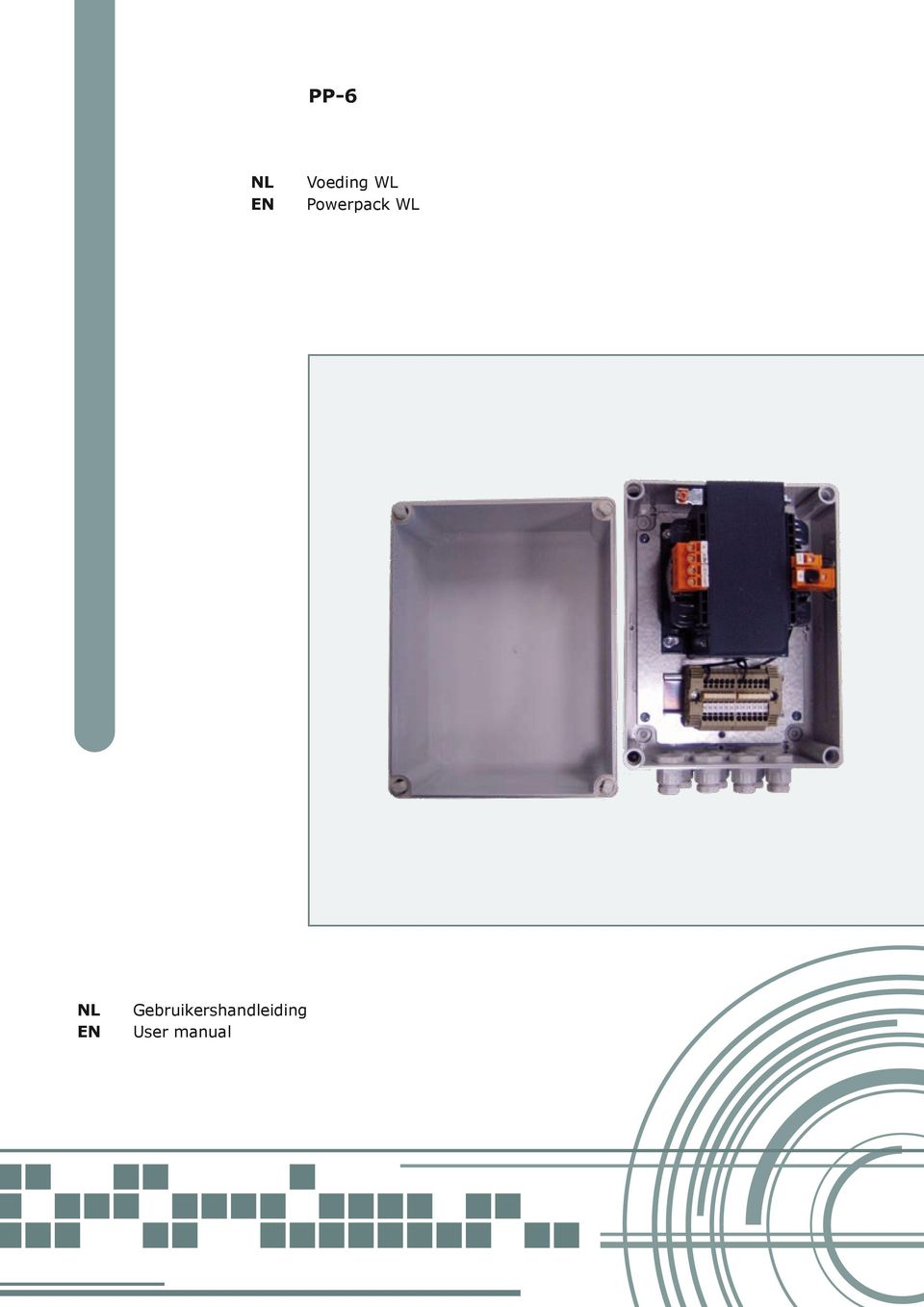
PP-6. Voeding WL Powerpack WL. Gebruikershandleiding User manual
|
|
|
- Casper de Ruiter
- 8 jaren geleden
- Aantal bezoeken:
Transcriptie
1 PP-6 NL EN Voeding WL Powerpack WL NL EN Gebruikershandleiding User manual
2 INHOUDSOPGAVE VOORWOORD...2 IDENTIFICATIE VAN HET PRODUCT...2 VEILIGHEIDSVOORSCHRIFTEN...2 TECHNISCHE GEGEVENS...2 ALGEMENE BESCHRIJVING...3 INSTALLATIE...3 VERHELPEN VAN STORINGEN...4 BESTELLEN VAN RESERVE-ONDERDELEN...4 Alle rechten voorbehouden. Niets uit deze uitgave mag worden verveelvoudigd en/of openbaar gemaakt door middel van druk, fotokopie, microfilm of op welke andere wijze dan ook, zonder voorafgaande schriftelijke toestemming van de fabrikant. Dit geldt ook voor de bijbehorende tekeningen en schema s. De in deze handleiding verstrekte informatie is gebaseerd op algemene gegevens aangaande de ons ten tijde van verschijnen bekende constructies, materiaaleigenschappen en werkmethoden, zodat wijzingen worden voorbehouden. Om deze reden dienen de gegeven instructies slechts als richtlijn voor het installeren, gebruiken, onderhouden en repareren van het op de voorzijde van dit document vermelde product. Deze handleiding is geldig voor het product in de standaard uitvoering. De fabrikant kan derhalve niet aansprakelijk worden gesteld voor eventuele schade voortvloeiend uit de van de standaard uitvoering afwijkende specificaties van het aan u geleverde product. Deze handleiding is met alle mogelijke zorg samengesteld, maar de fabrikant kan geen verantwoording op zich nemen voor eventuele fouten in deze handleiding of voor de gevolgen daarvan. NEEM DE TIJD OM DEZE HANDLEIDING ZORGVULDIG DOOR TE NEMEN ALVORENS HET PRODUCT TE GEBRUIKEN. BEWAAR DEZE HANDLEIDING STEEDS IN DE NABIJHEID VAN HET PRODUCT. NL /PP-6/010111/A

3 VOORWOORD Gebruik van de handleiding Deze handleiding is bedoeld als naslagwerk waarmee professionele, geschoolde en daartoe bevoegde gebruikers de PP 6 op veilige wijze kunnen installeren. Neem de tijd om deze handleiding zorgvuldig door te nemen alvorens de PP 6 te monteren. Bewaar de handleiding steeds in de nabijheid van het product. Pictogrammen en symbolen In deze handleiding worden de volgende pictogrammen en symbolen gebruikt: Suggesties en adviezen om de betreffende taken of handelingen gemakkelijker te kunnen uitvoeren. VOORZICHTIG Procedures die -wanneer ze niet met de nodige voorzichtigheid worden uitgevoerdschade aan het product, de omgeving of het milieu tot gevolg kunnen hebben. Verwante documentatie De volgende verwante documenten zijn verkrijgbaar: /WL /NCW 11 Nummer van de handleiding De handleidingnummers zijn opgebouwd uit vier velden: - veld 1: artikelnummer handleiding - veld 2: productnaam - veld 3: versienummer - veld 4: jaar van uitgave documentatie van deze producten opgenomen veiligheidsvoorschriften van toepassing. De gebruiker is te allen tijde volledig verantwoordelijk voor de naleving van de plaatselijk geldende veiligheidsvoorschriften en -richtlijnen. Ieder die aan of met het product werkt, dient van de inhoud van deze handleiding op de hoogte te zijn. Wijzig nooit de volgorde van de te verrichten handelingen. Het product is uitsluitend ontworpen voor het op het elektriciteitsnet aansluiten van een ingebouwde werklamp (WL) in de afzuigarm. Elk ander of verdergaand gebruik geldt niet als conform de bestemming. Voor schade of letsel dat hiervan het gevolg is, aanvaardt de fabrikant geen enkele aansprakelijkheid. Het product is in overeenstemming met de vigerende normen en richtlijnen. Gebruik het product uitsluitend in technisch perfecte conditie. Inspecteer het product en controleer het op beschadigingen. Bescherm het product tegen water of vocht. Gebruik het product nooit in een explosiegevaarlijke omgeving. Zorg ervoor dat op de werkplek voldoende goedgekeurde brandblussers aanwezig zijn. TECHNISCHE GEGEVENS Afmetingen Zie fig. 1. IDENTIFICATIE VAN HET PRODUCT Het identificatieplaatje bevat de volgende gegevens: A serienummer B productnaam C vermogen D aansluitspanning en frequentie (50/60 Hz) VEILIGHEIDSVOORSCHRIFTEN De fabrikant aanvaardt geen enkele aansprakelijkheid voor schade of letsel veroorzaakt door het niet (strikt) naleven van de veiligheidsvoorschriften en -instructies in deze handleiding, dan wel door onachtzaamheid tijdens installatie, gebruik, onderhoud en reparatie van het op de voorzijde van dit document vermelde product. Indien het product wordt gebruikt in combinatie met de eerder vermelde producten of machines (zie Verwante documentatie ), zijn eveneens de in de /PP-6/010111/A NL - 2

4 176 mm 145 mm A C D F 260 mm E B fig. 2 fig. 1 Elektrisch systeem Zie het identificatieplaatje en het separaat meegeleverde elektrische schema. Omgevingscondities Min. bedrijfstemperatuur 5 C Max. bedrijfstemperatuur 45 C Max. relatieve vochtigheid 80% ALGEMENE BESCHRIJVING Het product is speciaal ontworpen voor het op het elektriciteitsnet aansluiten van een in de afzuigarm ingebouwde werklamp (WL) met een maximum van totaal zes werklampen. De aansluitkast -die wordt gebruikt ten behoeve van een vaste installatie- is dan ook geschikt voor diverse aansluitspanningen en frequenties. Het product bestaat uit de volgende hoofdcomponenten (zie fig. 3): A afdekkap B behuizing C zekeringhouder D glaszekering E aansluitblok F transformator INSTALLATIE Uitpakken Controleer of het product compleet is. De inhoud van de verpakking bestaat uit: - aansluitkast PP 6 - gebruikershandleiding - elektrisch schema Indien onderdelen ontbreken of beschadigd zijn, neem dan contact op met uw leverancier. Installatie VOORZICHTIG Plaats het product niet op plaatsen waar het wordt blootgesteld aan trillingen of aan warmtestraling afkomstig van warmtebronnen. Respecteer de eerder beschreven omgevingscondities. Let bij het boren op eventueel aanwezige gas-, water- en elektriciteitsleidingen. Draai de bevestigingsschroeven (A) los en verwijder de afdekkap (zie fig. 4). Bevestig de behuizing met behulp van vier bouten tegen de muur. In de behuizing zijn hiertoe montagegaten (B) aangebracht (zie fig. 4). Sluit de PP 6 elektrisch aan: - netvoeding ( MAINS ) - werklamp (WL) (max. 6) NL /PP-6/010111/A

5 B 180 mm 130 mm A fig. 3 Elektrische aansluiting A B VOORZICHTIG Vergewis u ervan dat het product geschikt is voor aansluiting op het plaatselijke net. Gegevens met betrekking tot de aansluitspanning en frequentie vindt u op het identificatieplaatje. Aansluiting van de bekabeling dient te geschieden in overeenstemming met de ter plaatse geldende voorschriften en is uitsluitend toegestaan aan daartoe opgeleide, bevoegde service-technici. fig. 4 VOORZICHTIG Voorkom schade. Let bij het aansluiten op de kleurcodes. Netvoeding ( MAINS ) Voer het netsnoer door de doorvoerwartel (A) en sluit het aan conform het meegeleverde elektrische schema (zie fig. 5). Draai de wartelmoer aan. Werklamp (WL) Voer de voedingskabel (NCW 11) door de doorvoerwartel en sluit de kabel aan op het aansluitblok (B) (zie fig. 5) Draai de wartelmoer aan. VERHELPEN VAN STORINGEN Voor het verhelpen van storingen die betrekking hebben op het niet (correct) functioneren van de WL, zie de betreffende handleiding. Wanneer u eventuele overige problemen niet zelf kunt verhelpen, neem dan contact op met uw leverancier. BESTELLEN VAN RESERVE- ONDERDELEN De voor het product leverbare reserve-onderdelen vindt u in fig /PP-6/010111/A NL - 4

6 1 3 2 fig. 5 Richt uw bestelling aan uw leverancier en vermeld altijd onderstaande gegevens: - productnaam, aansluitspanning en serienummer (zie het identificatieplaatje) - artikelnummer van het betreffende onderdeel (zie het elektrische schema) of - positienummer van het betreffende onderdeel (zie fig. 6) - benaming - aantal fig. 6: Pos.nr. Benaming Opmerkingen 1 glaszekering - 2 aansluitblok - 3 transformator - NL /PP-6/010111/A
 of - positienummer van het betreffende onderdeel (zie fig.")
7 TABLE OF CONTENTS PREFACE...7 IDENTIFICATION OF THE PRODUCT...7 SAFETY INSTRUCTIONS...7 TECHNICAL SPECIFICATIONS...7 GENERAL DESCRIPTION...8 INSTALLATION...8 TROUBLESHOOTING...9 ORDERING SPARE PARTS...9 All rights reserved. No part of this publication may be copied or published by means of printing, photocopying, microfilm or otherwise without prior written consent of the manufacturer. This restriction also applies to the corresponding drawings and diagrams. The information given in this document has been collected for the general convenience of our clients. It has been based on general data pertaining to construction material properties and working methods known to us at the time of issue of the document and is therefore subject at any time to change or amendment and the right to change or amend is hereby expressly reserved. The instructions in this publication only serve as a guideline for installation, use, maintenance and repair of the product mentioned on the cover page of this document. This publication is to be used for the standard model of the product of the type given on the cover page. Thus the manufacturer cannot be held responsible for any damage resulting from the application of this publication to the version actually delivered to you. This publication has been written with great care. However, the manufacturer cannot be held responsible, either for any errors occurring in this publication for their consequences. TAKE YOUR TIME TO CAREFULLY READ AND UNDERSTAND THE MANUAL BEFORE USING THE PRODUCT. ALWAYS KEEP THE MANUAL WITH THE PRODUCT. EN /PP-6/010111/A

8 PREFACE SAFETY INSTRUCTIONS Using this manual This manual is intended to be used as a work of reference for professional, well trained and authorised users to be able to safely install the PP 6. Take your time to carefully read and understand the manual before mounting the PP 6. Always keep the manual with the product. The manufacturer does not accept any liability for damage to the product or personal injury caused by non-observance of the safety instructions in this manual, or by negligence during installation, use, maintenance and repair of the product mentioned on the cover of this document. Pictograms and symbols The following pictograms and symbols are used in this manual: Suggestions and recommendations to simplify carrying out tasks and actions. CAUTION Procedures which, if not carried out with the necessary caution, caution, could damage the product, the workshop or the environment. Related documentation The following related documents are available: /WL /NCW 11 Manual number The manual number consists of four fields: - field 1: article number manual - field 2: product name - field 3: version - field 4: year of issue IDENTIFICATION OF THE PRODUCT The identification plate contains the following data: A serial number B product name C power D supply voltage and frequency (50/60 Hz) If the product is used in combination with the earlier mentioned product or machines (see Related documentation ), the safety instructions in the documentation of these products also apply. The user of the product is always fully responsible for observing the local safety instructions and regulations. Everyone working on or with the product, must be familiar with the contents of this manual. Never change the order of the steps to perform. The product has been designed especially to connect an in the extraction arm integrated working light (WL) to the electricity supply. Using the product for other purposes is considered contrary to its intended use. The manufacturer accepts no liability for any damages or injury resulting from such use. The product has been built in accordance with state-of-the-art standards and recognised safety regulations. Only use the product in technically perfect condition. Inspect the product and check it for damage. Protect the product against water and humidity. Never use the product in an explosive environment. Make sure that the workshop contains sufficient approved fire extinguishers. TECHNICAL SPECIFICATIONS Dimensions See fig /PP-6/010111/A EN - 7

9 A C D 176 mm 145 mm F 260 mm E B fig. 2 fig. 1 Electric system See the identification plate and the separately supplied electric diagram. Ambient conditions Min. operating temperature 5 C Max. operating temperature 45 C Max. relative humidity 80% GENERAL DESCRIPTION The product has been designed especially for connecting an in the extraction arm integrated working light (WL) to the mains, with a maximum of six working lights. The control box -which is used for a fixed installation- can be used for various supply voltages and frequencies. The product consists of the following main components (see fig. 3): A cover B housing C fuse holder D glass fuse E connecting block F transformer INSTALLATION Unpacking Check that the packing is complete. The packing should contain: - control box PP 6 - user manual - electric diagram If parts seem to be missing or damaged, contact your supplier. Installation CAUTION Do not position the product in places where it is exposed to vibrations or heat radiation from heat sources. Observe the earlier given ambient conditions. When drilling the holes note any gas, water and electricity lines. Loosen the mounting screws (A) and remove the cover (see fig. 4). Attach the housing using four screws against the wall. For this purpose mounting holes (B) have been provided in the housing (see fig. 4). Connect the PP 6 electrically to: - mains supply ( MAINS ) - working light (WL) (max. 6) EN /PP-6/010111/A

10 B 180 mm A 130 mm fig. 3 Electric connection A B CAUTION Make certain that the product can be connected to the local mains. Specifications with respect to supply voltage and frequency can be found on the identification plate. Connect the wiring in conformance with the regulations. Connecting the product is reserved to well-trained and authorised service engineers. Mains supply ( MAINS ) Feed the supply cable through the grommet (A) and connect it in accordance with the supplied electric diagram (see fig. 5). Tighten the cap nut. Working light (WL) Feed the supply cable (NCW 11) through the grommet and connect the cable to the connecting block (B) (see fig. 5). fig. 4 CAUTION Prevent damage. Note the colour codes when connecting. Tighten the cap nut. TROUBLESHOOTING For remedying errors which apply to not (correctly) functioning of the WL, see the corresponding manual. If you cannot remedy any other problems, contact your supplier. ORDERING SPARE PARTS The spare parts available for the product are given in fig /PP-6/010111/A EN - 9
 Feed the supply cable through the grommet (A) and connect it in accordance with the supplied electric diagram (see fig. 5). Tighten the cap nut.")
11 1 3 2 fig. 5 Address your order to your supplier and always state the data below: - product name, supply voltage and serial number (see the identification plate) - article number of the particular part (see the electric diagram) or - position number of the particular part (see fig. 6) - description - quantity fig. 6: Pos. no. Description Remarks 1 glass fuse - 2 connecting block - 3 transformer - EN /PP-6/010111/A
 or - position number of the particular part (see fig. 6) - description - quantity fig. 6: Pos. no.")
12 /010111/A
